

The main parts, a centrifugal pump consist of are casing, impeller, shaft, bearing, and sealing.


Casing
The centrifugal pump’s casing (fig 1.) houses the hole assembly and protects is from harm as well as forces the fluid to discharge from the pump and convert velocity into pressure.


The casings design does not influence TDH but is important to reduce friction losses. It supports the shaft bearings and takes the centrifugal forces of the rotating impeller and axial loads caused by pressure thrust imbalance.
Most of all centrifugal pumps are of simple spiral casing and are not equipped with a guide vane aperture. Even if this would increase efficiency due to the simplicity of spiral casings, this is the preferred type of construction. Only extraordinary big or multistage pumps do have guide vanes. The spiral pump casing has to be carefully designed to avoid turbulences resulting in a decrease in efficiency.
The shape of the casing is defined by several factors; these are profiles angles, diameter and width. The whole amount of fluid flows through the discharge cross section, the amount of fluid is decreasing when going backwards in the spiral, from point of view of flow direction.
Therefore the area of the profiles is decreasing continuously as well, to fit the flow rate in the specific point of the pump casing. The result is a spiral shaped casing. The optimum properties of the spiral were found in experiments and expressed in formulas and diagrams. The fluid velocity is not constantly distributed over a certain profile section.
Modern centrifugal pumps are designed for a constant pressure and constant mean velocity in every profile section at the BEP. Apart from the BEP, the radial forces are out of balance resulting in a total radial force different to zero. This is important because the radial force bends the pump’s shaft and results in higher wear at seals and could lead to shaft fatigue.
To reduce most radial forces the pump casing can be designed as a double spiral casing. In this case the flow is spitted into two parts. Due to symmetry reasons almost all radial forces chancel each other out. Another important part of the pump’s casing are elbows in multistage pumps to deflect the flow from the previous stages discharge side to the suction side of the following. If a multistage pump is equipped with guide vanes, no elbows are necessary.


As already mentioned, guide vane construction is only common at big or horizontal multistage pumps. Guide vanes work as a diffuser and convert the increased fluid velocity into pressure. It consists of extending channels arranged around the impeller. To ensure adequate pump life time, the pump’s casing material should be selected carefully. Standard pump casings are made of cast iron but due to the fact that cast iron is not that resistant against cavitation, many pumps are coated or made from more wear resistant materials.
Due to vibrations the casing should have good damping properties. Pump casings are splitted either axial or radial to allow assembling and maintenance.
Impeller
The impeller is the essential part of a centrifugal pump. The performance of the pump depends on the impeller diameters and design. The pump’s TDH is basically defined by the impeller’s inner and outer diameter and the pump’s capacity is defined by the width of the impeller vanes. In general, there are three possible types of impellers, open, enclosed and semi open impellers, each suitable for a specific application. Standard impellers are made of cast iron or carbon steel, while impeller for aggressive fluids and slurries require high end materials to ensure a long pump life.
Open impeller
Open impellers (fig.2) are the simplest type of impellers. They consist of blades attached to the hub. This type of impeller is lighter than any of the other type at the same diameter.


Weight reduction leads to less force applied to the shaft and allows smaller shaft diameters. These results in lower costs compared to equivalent shrouded impellers. Typically, open impellers operate at higher efficiency because there is no friction between the shrouds and the pump casing. On the other hand side, open impellers have to be carefully positioned in the casing. The gap between the impeller and the surrounding casing should be as small as possible to maximise efficiency.
As the impeller wears the clearance between the impeller and the front and back walls open up, what leads to a dramatic drop in efficiency. A big problem when using a pump with an open impeller are abrasives. Due to the minimized clearance between blades and casing, high velocity fluids in close proximity to the stationary casing establish vortices that increase wear dramatically.
Semi-open impeller
Semi-open impellers can be seen as a compromise between open and enclosed impellers. A semi-open impeller is constructed with only one shroud, usually located at the back of the impeller. It usually operates at a higher efficiency than an equivalent enclosed one due to reduced disc friction as there is only one shroud.
A big advantage of semi-open impellers compared to open ones is that the impellers axial position can be adjusted to compensate for wear. A problem is that the entire backside of the impellers shroud is under full impeller discharge pressure as the front side is under suction pressure increasing along the impeller radius due to centrifugal force.
The differential between these pressures causes an axial thrust imbalance. Manufactures try to reduce this effect by applying vanes to the back side of the impeller. But the efficiency of these so called “pump out vanes” decreases if the impeller is moved forward to compensate for wears. A better option to compensate the loss of efficiency is an adjustable wear plate, so that clearance adjustments can be made.
Semi-open impellers are also easily to manufacture as all sides of the impeller are easy accessible for manufacturing processes as well as for applying surface hardening treatments. In combination with wear compensation applications, semi‐open impellers can be used for intermediate abrasive fluids.
Another advantage if using semi closed impellers in combination with an adjustable wear plate compared to an open impeller equipped with the same wear compensation system is vane support. This prevents the vanes from collapsing or deformation when using it with fluids contaminated by solids. This justifies the application of semi‐open impellers even thought it seems logically to use an open impeller due to its reduced weight.
Enclosed impeller


Enclosed impellers (fig 3.) consist of blades covered by a front and back shroud. The fluid steams through the impeller without interacting with the stationary pump casing. In a well designed enclosed impeller, the relative velocity between the fluid and the impeller walls at any given radius is rather small. The disc friction of the shrouds rotating in close proximity to the pump casing causes a lower efficiency as comparable semi-open or open impellers.


A problem when dealing with enclosed impellers is leakage between the impeller shrouds and the pump casing back to the suction side of the pump. There are two common ways for controlling leakage in enclosed impeller pumps (fig 4).
One are wear rings in combination with impeller balance holes. But the tight clearance between the rotating and the stationary wear ring causes high fluid velocities and therefore a high wear rate. Wear ring lifespan is unacceptable short in an abrasive environment. If wear rings reach the end of their intended lifespan, it has to be replaced because if it is not the high velocity zone can shift from the wear ring into the impeller thrust balance holes. This could cause significant damage to the impeller and may result in an expensive repair or replacement of the impeller. So this is only an option when dealing with moderate abrasive fluids with light solids only.
The other possibility to control wear and axial thrust balance are pump‐out vanes. These pump‐out vanes cause much lower local velocities spread over a bigger area resulting in lower wear. It is not uncommon, that pump‐out vane lifespan equals or exceeds the main impeller’s lifespan. The major disadvantage of pump out vanes is their power consumption what leads to a lower efficiency.
Overall pump‐out vanes provide a good pump characteristic when dealing with abrasive solids. Another problem when operating an enclosed impeller in combination with fluids contaminated by large solids like rocks is that it may happen that a piece of solid gets caught in the impeller eye outlet. This may cause a mechanical or hydraulically imbalance and has the potential to damage the pump. In an open or semi‐open impeller this rock would be broken by the grinding between the rotating impeller and the stationary casing. To remove the blockage disassembling of the pump would be necessary.
Shaft
The shaft is the connection between impeller and drive unit which is in most cases an electric motor but can also be a gas turbine. It is mainly charged by a radial force caused by unbalanced pressure forces in the spiral casing and an axial force due to the pressure difference between front and backside of the impeller. Most common pump shafts are made of carbon steel. There are several cranks to support the bearings and seals.
A high surface quality and small clearances are required. Especially in the areas of the bearing’s, clearance and surface quality is important to ensure right positioning of the shaft in the casing and therefore close positioning clearances of the impeller. At the area of the seals, particularly the surface quality is important to ensure an adequate seal lifespan. In shaft design it is also important to avoid small radiuses at cranks to minimize stress in these areas which are susceptible for fatigue.


Bearings
The bearings keep the shaft in place to ensure radial and axial clearance. Some approximate bearing properties can be seen in fig 6


. The bearings lead radial and axial forces from the impeller into the casing. In double suction pumps bearings are located at both sides of the impeller as at single suction pumps all bearings are located behind the impeller. In horizontal process pumps, usually oil bath lubricated bearings are used.
Medium and heavy duty process pumps are used in refineries, where highest reliability is required. In these pumps axial loads are supported by universal single row angular contact ball bearings. In heavy duty process pumps, also matched taper roller bearings with steep contact angles, arranged face to face or back to back are used to support combinations of high radial and axial loads.
In very high duty service and slurry pumps, spherical roller bearings can be used to support very high radial loads. A spherical thrust bearing is used to support axial loads. It is usually spring preloaded to ensure that sufficient load is applied during start up or pump shutdown. At vertical pumps, the thrust bearing can be a ball bearing with a spherical outer ring raceway, with the centre of the radius located on the bearing axis, providing a self‐alignment capability.
It is equipped with a 45° contact angle that enables the bearing to support large axial loads and moderate radial loads. If the pump is operated at its BEP, the bearing will only have to carry the rotating assemblies’ weight, the stress due to interference fit of the shaft and in some cases manufacturer dependent preloads. Unfortunately, many bearings are overloaded because of wrong interference fit, shaft bend, solids, unbalanced rotating elements, vibrations, axial thrust and many more.
This leads to increased stress and temperature and therefore to a decrease in lifespan. It is also important for the bearing’s lifespan to protect it from fluid by adequate seals.
Sealing
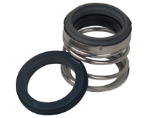
To protect the bearings against fluid and prevent leakage, there are several seals fitted into the casing. Nowadays, rotary pumps are equipped with mechanical seals (fig.7). A mechanical seal consists of primary and secondary sealing. In most cases the primary part, which is fitted to the casing, is made of a hard material like silicon carbide or tungsten carbide.


The other, the rotating part of the primary seal is made of a soft material like carbon. Both parts are pressed against each other by e.g. a spring. The secondary sealings are not rotating relative to each other and provide a fluid barrier. Mechanical seals can be separated into pusher/non‐pusher seals, seal driving/spring compression, balanced/unbalanced and inside/outside mounting.
Pusher seals will have a tendency to “hang up” when handling fluids which crystallize because the secondary seal member is not able to accommodate for travel. Whether applying a balanced or unbalanced seal will effect seal performance. Unbalanced seals see a high pressure at the impeller side and therefore have a reduced fluid film between the seal faces. This leads to overheating, rapid face wear and seal fatigue at early stages. To simplify maintenance many seals are available in cartridges which are pre‐packed seal assemblies.

To avoid any leakage when handling hazard fluids, double or tandem seals can be applied. In these seals, a secondary so called containment seal is placed after the primary one. The space in between is filled with a natural fluid called barrier or buffer fluid. These seals are very common in the petroleum industry.
The difference between a tandem and a double seal is that in a double seal the barrier fluid is pressurised. Due to this, in case of primary seal fatigue the pressurised barrier fluid streams into the pumps instead of the hazard fluid into the atmosphere. The seal materials must fit the fluid to ensure accurate seal lifespan. The standards of modern mechanical seals are widely defined by API Standard 682 ‐ Shaft Sealing Systems for Centrifugal and Rotary Pumps.


One Reply to “Centrifugal Pump Assembly”
Comments are closed.