

Sand control screens are design to retain the formation sand, they have slots that are narrower than the largest sand grains. Thus, the slots of the sand control screens are not much larger than the largest pores in the reservoir rock.
This means that an operation where the drilling mud must be able to plug the largest pores in the formation sand without plugging slots of the sand control screens, requires very careful planning and control, both of the drilling mud, and of the slot width of the sand control screens. The risk of plugging the sand control screens will be high. For the safe execution of such operations a good understanding of the plugging mechanism is required. One must be able to predict the screen slot width that is required to avoid plugging by a mud with a certain particle concentration and particle size distribution. It would also be useful if one could predict the volume of drilling mud that could pass through a certain screen without plugging it.
When the sand control screen and drilling mud have been chosen, the particle size and concentration of the drill cuttings in the mud must be carefully controlled when drilling through the reservoir. The size of the mud solids can be controlled most easily during drilling by changing the screen in the shale shakers. For this reason it is very important to know what size of openings in the shale shaker screens are required to avoid plugging of a certain sand control screen.
The importance of screen plugging. The plugging of sand control screens by drilling muds is important for at least two reasons:
- If the sand control screen is plugged completely or partially with drilling mud, the productivity of the well is reduced, and costly operations involving clean-up fluids and dissolvers may be required.
- If the sand control screen is partially plugged by drilling mud, the local velocity through the screen slots may become high enough to cause erosion of the screens and uncontrolled sand production.
There are no published data available that quantitatively describes the erosion of sand control screens, but preliminary results from ongoing work suggest that differential pressures of more that 1-2 bar across a partially plugged screen may cause an unacceptably high erosion rate.
General plugging theory for sand control screens. Drilling muds are designed to block the surface of the pores in the reservoir rocks without particle invasion into the pores. When large pores or other openings are plugged, initially the largest particles in the drilling mud forms arches across the opening. Then the openings in the arches are filled and stabilized by smaller particles and with clays, polymers, emulsions or other material that is present in the mud.
Thus, if one wants to understand how sand control screens are plugged by drilling muds, it is first necessary to understand how particles are retained by sand control screens. C. J. Coberly did some pioneering work in the area of screen plugging in the 1930’s, and published his results in 1937. He did experiments with steel balls, uniform sands, and a large range of reservoir sands and mixture of particles of various sizes. He used an experimental apparatus with one single slot, and where the slot width could be adjusted by a micrometer screw. Stable arches were defined as arches that would reform more or less immediately when they were disturbed. He found that stable arches would form across slots when the ratio between slot width and particle size was less than 2. If the ratio was larger than 2, unstable arches would form. These would only reform after a large number of particles had passed through the slot. For uniform sands, no arches at all would form if the ratio was higher than 3. The properties of mixtures with varying particle size were dominated by the largest particles, as long as the fraction of large particles was sufficiently high. For actual reservoir sands, Coberly found that stable arches would form if dw (the theoretical sieve size that would retain 10% by volume of the sand grains) of the formation sand was greater than half the screen slot width.
Some of this work was later repeated by McCormack [3], who generally confirmed Coberly’s conclusions. He also reported that arches consisting of 3 particles tended to be stable, while arches consisting of 4 or 5 particles were unstable.
Extrapolating this work to drilling muds, it can be expected that, for a specific mud with a certain particle size distribution, stable arches will be formed and cause immediate plugging of narrow slots. Then, when the slot width increases one should expect to see unstable arches resulting in partial plugging, until the slots are too wide for arches to form at all and no plugging will be observed.
For prepacked screens the situation is slightly different. They will be plugged not only by a filter cake that forms on the screen surface, but also by particles that invade the layer of prepacked gravel and are trapped inside it. Thus it should be expected that pre-packed screens will be plugged more easily than single wrapped screens, and that the plugging will be more permanent.
Characterization of screen plugging by drilling fluids. The plugging of sand screens by drilling fluids is difficult to predict. The broad range of particle size makes it difficult to model the bridging across the slots. The bridging is a function of particle size distribution relative to the slot width. Therefore, in any single measurement of plugging can appear to be a random process. However, a series of measurements can show definite trends.
The quantity of mud needed to plug a screen can be determined experimentally. The volume of mud required to plug a screen can be represented by the length, H, of a mud column that has passes through the screen when it plugs. This length represents the volume per unit area of the screen.
The practical importance of this parameter can be shown by further defining a term, Aplug that represents the percentage of the total area of a screen that is plugged by solids when a drilling fluid has been produced through the screen. When (do – di)/2 is the width of the open annulus outside the screen, the largest fraction of the screen that can be plugged by back production of a certain drilling mud can be predicted by the formula:
Aplug=(do – di)/2H
For example, if the mud column required to plug the screen is 50 cm, and the annulus clearance is 2.5 cm the Aplug is 5%.
Factors affecting screen plugging. The plugging of sand control screens by drilling fluids can be expected to be a function of many factors including screen type and geometry, mud type and rheology, mud velocity, mud solids concentration and the particle size distribution of the mud solids. All of these factors have been addressed to some extent in the present work, but the main emphasis has been on particle concentration and particle size distribution.
Sand Screen Evaluation Procedures.
A dedicated sand screen evaluation loop was developed for this study. Except for a few tests that were done on previously existing hardware all the remaining tests were done on the dedicated loop. The dedicated system was based on the knowledge gained from the initial testing.
These initial tests were performed in a cell used for sand production evaluation on sand screens. This cell is described elsewhere. The results of these tests are summarized in Table 1. The pressure drop across the sand screen was recorded as a function of time at ambient temperatures. The and plugging was defined on the time to reach a prescribed pressure drop limit. In the case of these initial studies screen plugging was based on a 3000 mbar pressure drop across the screen.
Dedicated System. The dedicated laboratory test facility, as shown in the schematic drawing in Figure 1, was used for subsequent studies. Circular sections of sand control screens were fitted inside a test cell that is mounted in the heating sleeve of a standard high pressure fluid loss cell. A heating element with a thermostat is installed in the mud reservoir, and the pipes are insulated to prevent cooling of the mud during circulation. The mud reservoir contains approximately 10 litters. It has an agitator fitted very close to bottom to prevent settling of mud solids during an experiment.
The pressure differential between the two sides of the screen is logged, as well as the mud temperature at the outlet of the cell and the flow rate through the system. The temperature for the measurements was maintained at 50°C. The first set of experimental results are presented in Table 2. Due to limitations in the pressure transducer, the plugging pressure was defined either as 2000 mbar or to 7000 mbar. The remaining studies presented in Tables 3 through 6 were based on 7000 mbar pressure drop across the sand screen.
In the latter four series of tests the sand screen slot widths varied from 250, 200, 150 and 100 microns. Once the mud reservoir had been filled with a mud sample, all four screens were tested without changing the mud. The screen with the largest slot width was always tested first, and all the mud contained in the test cell and the filter cake from the screen surface was returned to the reservoir before a smaller screen was tested. The temperature for the measurements was maintained at 50°C. This test sequence was repeated two or more times for each mud type with varying flow rate. Three flow rates of approximately 25, 50 and 100 ml/min were used.
The experiments were stopped once the differential pressure across the screens had increased above 7000 mbar. Differential pressures larger than 7000 mbar could not be logged due to limitations in the pressure transducers. If plugging did not occur, the experiments were continued until the differential pressure across the screen had been stable for at least 30 minutes.
Interpretation of the Results. The interpretation of the data can be rather complex and often is based on qualitative evaluations. During the initial testing three different degrees of plugging were observed. The pressure drop across the sand screen for each tests can vary over a broad spectrum of results. Although difficult to do this spectrum results were described in a few categories as follows.
- No plugging, as shown in Figure 2, where the differential pressure over the screen does not increase with time, and the differential pressure is stable with no large fluctuations. This must be interpreted as a situation where all the particles in the mud are able to pass through the screen slots without being trapped.
- Little plugging, as shown in Figure 3, where the was pressure drop across the screen increased, usually with fluctuation, but failed to reach the pressure limits within the testing period. This must be interpreted as the starting phase of plugging where some initial arches across the slots were forming and breaking. It must be assumed that this would have evolved into unstable plugging if the volume of the mud reservoir had been larger.
- Unstable plugging, as in Figure 4, where the differential pressure increases with time, but fluctuates significantly. This is interpreted as a situation where unstable arches of more than one particle are formed across the screen slots, and some of the arches break down occasionally when they are stressed by the increasing differential pressure.
- Nearly stable, as shown in Figure 5, where the differential pressure drop show some fluctuation prior to stabilizing above the pressure limits of the instrumentation. This represents a situation where some break down of arches occurred before becoming stable.
- Stable plugging, as in Figure 6, where the differential pressure increases rapidly without large fluctuations. Stable plugging occurs where a large fraction of the particles in the mud are retained by the screen, and where stable arches are formed across the screen slots (or inside the pre-pack).
These descriptions could be broadened to include more categories but that would ultimately lead to a one category for almost each experiment.
Evaluation with non-water based muds.
Initial testing. In October 1994 some initial tests were performed for a standard oil-based field mud. Most probably, 150 mesh shaker screens were in use when the sample was taken. Unfortunately, no information on mud density, particle concentration or particle size distribution was available.
The mud was tested against three different screen types. There were 150 and 200 micron single wrapped screens delivered by the manufacturer. These screens are made from heavy wire and need no base pipe support. A 300 micron screen with a resin coated 20-40 mesh pre-pack delivered by service company was tested. The results of these tests are contained in Table 1.
Because of instrument limitations a pressure drop of 3000 mbar was used for establishing stable plugging. In this study stable plugging occurred only with the pre-packed screen. Since a single wrapped screen with 200 micron slots is not plugged by the same mud, and the slots of the outer layer of the pre-packed screen are 300 micron wide, the plugging must occur in the pre-pack itself.
Based on these results it was decided to concentrate on single wrapped screens, without pre-pack, for the rest of the experiments. The remaining work in this study was based on single wrapped screens that were designed without base pipe support.
Early 1995 the dedicated laboratory equipment was ready. At the same time the quality of the shale shakers on a semi-submersible drilling rig were being evaluated. The shale shakers on this rig could not handle screens that were finer than a mixture of 120 and 150 mesh. It was not known whether this was sufficient to avoid plugging 200 micron sand control screens and this needed to be evaluated.
A sample of a polyalphaolefin (PAO) invert emulsion drilling mud delivered from the rig was tested for plugging against a sand control screen with 200 micron slots. The screen samples were rod based screens without base pipe. The results were compared with similar tests on a sample of ester based fluids from another semi-submersible drilling rig, which was supposedly using 200 mesh screens in the shale shakers. The results of these tests are contained in Table 2. These results opened the possibility that some effects of velocity of these synthetic based fluids through the screens. However the higher velocities were with P AO mud and the A 1 &:: lower velocities were with ester based mud.
Further studies were done on an ester based field mud drilling were done wire wrapped screens with slot widths of 250, 200, 150 and 100 microns. These studies were used for expanded evaluations on the effects of fluid velocity through the sand control screens. These fluids were tested on the same hardware illustrated in Figure I. However, in these studies the differential pressure sensors had a limit of 7000 mbars. The results of these tests are contained in Table 3.
The ester mud sample had been used for drilling the reservoir section a well and the mud had been circulated through a mixture of 200 and 165 mesh shale shaker screens. A 200 mesh shaker screen has 74 micron openings and a 165 mesh shaker screen has 90 micron openings. The volume of suspended solids was 24.3%.
The ester based mud caused stable plugging of the 100 micron screen, and unstable plugging of the 150 and 200 micron screens. The 250 micron screen was either not plugged (1 experiment), or unstable plugging was observed (3 experiments). The column of mud required to plug the screens varied between 9 and 199 cm for the ester based mud. This corresponds to a maximum plugged area, A plug• of between 1 and 29 % for the 2.5 cm annulus. Based on the assumption that sand control screen is not likely to be a problem when less that 5% of the screen is plugged, this ester based mud could be used with slot widths down to 150 micron.
For the ester mud the high fluid velocity tests generally gave higher H values than the low velocity tests (see Table 3). But since all the high velocity tests were performed with one mud sample and all the low velocity tests with another, it is not possible to tell for sure if this is a true effect of velocity, or a result of a high concentration of coarse particles in one of the samples.
Evaluation with Potassium Chloride Muds.
A more detailed evaluation of the effects of fluid velocity was done with a KCl water based drilling fluid. This KCl mud contained xanthan polymer, bentonite and some proprietary products. It was weighted to a density of 1500 kg/m3 with standard barite. The mud contained 13.9% particles by volume as calculated as the sum of barite and bentonite. This mud was tested against four different sand control screens with slot widths of the of 100, 150, 200 and 250 micron. The results of these tests are shown in Table 4. This mud was mixed by a mud company, but had not been used for drilling. It had not been passed through any screens or shale shaker before testing.
This 1500 kg/m3 KCI mud caused essentially stable plugging of the 100 and 150 micron sand control screens. Unstable plugging generally occurred on the 200 micron screen with one example of nearly stable plugging. The 250 micron screen was either no plugging (3 experiments), unstable plugging (2 experiments) or little plugging (1 test). The column of mud required to plug the screens varied between 7 and 568 em for the water based mud. This corresponds to a maximum plugged area, Aplug• of between 37 and 0.4 %. Based on the 5% plugging assumption the KCl mud will only be safe with slot widths that are 250 micron or more.
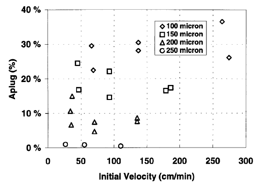
The 1500 kg/m3 KCl mud was tested at several velocities, and with many different mud samples. In Figure 7 the Aptug of the 100, 150 and 200 micron sand control screens are plotted as a function of initial velocity through the screen slots. The velocity of the fluid through the slots would increase as the screen plugged. There were no discernible effects of fluid velocity on the plugging of the screens.
Based on these tests it was decided that the effect of mud velocity could be ignored for the rest of the work.
The effect of shaker screens and particle concentration. A goal of this study was to describe a relationship between the shale shaker screen hole size and the resultant tendency of the drilling fluid to plug the sand control screen. As part of this study the effects of particle concentration, in the form of weighting agent, was to be determined. To do this study two muds of the same type of KCl mud used above were evaluated. They had a density of 1200 kg/m3 and 1800 kg/m3.
In addition to evaluate the importance of mud conditioning prior to running the screens were evaluated. Therefore, samples of each of these muds were conditioned through a 150 mesh shaker screen. A portion of the resultant muds was conditioned further through a 200 mesh shaker screen. The original 1200 kg/m3 mud contained 4.6% by volume of particles as calculated from the sum barite and bentonite. The original1800 kglm3 mud contained 23.3% by volume of particles as calculated from the sum barite and bentonite. The particle size distribution of the original and conditioned muds were measured on a laser particle analyzer.
The unconditional and conditioned muds at 1200 and 1800 kg/m3 were tested against four different sand control screens with slot width of the 100, 150, 200 and 250 micron. The same conditions as above were used with the 7000 mbar limit. The results are contained i’1 Tables 5 and 6 respectively for the 12Cfl and 1800 kg/m3 muds.
For the 1200 kg/m3 mud both the effects of screen slot width and conditioning though shaker screens are observed. As the muds have a relatively low level of suspended solids none of these muds exhibited stable plugging, even on the narrow slot width of 100 microns. However, two of the tests resulted in nearly stable conditions with this narrowest slot width. Other than those two, the unconditioned mud and the two conditioned muds exhibited unstable plugging on both the 100 micron screen and the 150 micron screen. Generally, the time required for this unstable plugging increased as the shaker screen size decreased. With the 200 micron slot screen only the original unconditioned mud showed signs of plugging. The conditioned muds does not exhibit any form of plugging. Likewise, none of these muds showed any sign of plugging on the largest slot width of 250 microns.
The results with the 1800 kglm3 mud also illustrate the effects of slot width and conditioning through the shaker screens. However, as these muds have considerable higher level of suspended solids, the effects of these increased solids is clearly demonstrated. Only the unconditioned mud clearly showed stable plugging of the sand control screens. This stable plugging occurred with both the I 00 micron and 150 micron screens. With the wider slot widths of 200 micron and 250 micron unstable plugging occurred with this unconditioned mud. The time to this unstable plugging increased with slot width. For the mud conditioned through the 150 mesh shaker screen unstable plugging took place with the 100 micron, ISO micron and 200 micron slot width. Again the time to plugging increased with increasing slot width. With the 250 micron slot screen no plugging was observed. With the mud conditioned through the 200 mesh shaker screen unstable plugging occurred only with the 100 micron and 150 micron slot width screens. The time to plugging increased with the larger slot width. For the wider two slot widths no plugging was observed with this mud.
These results demonstrate three trends which could be anticipated for the back production of muds through the sand control screens. First, the wider slot width is less likely to plug. Second, the use of finer shaker screens makes it less likely the sand control screens will plug. Third, the mud with the lower suspended solids level is less likely to plug. These trends are clearly illustrating in Figure 8 where the observations for the 1200 kg/m and 1800 kg/m 3 are summarized. In addition the trends for the unconditioned muds including the 1500 kg/m are also illustrated in this figure.
Using the criteria that plugging of the sand control screen is not likely to be a problem if the maximum plugged area, Aplug• is less than 5%, the results of the above evaluation leads to several operational considerations. Based on this criterion one can see from the data i~ Tables 5 and 6 that the lower solids level of the 1200 kg/m has advantages. When either shaker screen was used there was less that 5% blocking with all but the 100 micron slot width. Even with this narrowest slot width the unstable plugging was at the limit of this criterion with these conditioned muds. With the unconditioned mud this criterion was achieved only with the 250 micron and 200 micron slot width.
When using the 1800 kg/m mud, meeting this requirement was more problematic. When the 200 mesh shaker screen was used with this heavier mud, this criterion was achieved with all slot widths except 100 micron. With the larger 150 mesh shaker screen this criterion was met with only the 200 micron and 250 micron slot width. The unconditioned mud met this requirement only with 250 micron slot width.
The plugging of the sand control screen is a directly related to the conditioning of the mud with the shaker screens. The average area of the screen that would be plugged in the 2.5 cm annulus is illustrated in Figures 3 9 and 10 respectively for the 1200 kg/m and 1800 kg/m KCI muds. Generally, the A plug• of plugged sand control screens is effected by both the shaker screens and slot width. The area clearly show both the effects of the removal of the upper range of particle size solids with the shaker screens and the increased solids content of the heavier mud. For the same particle size cut-off the 1200 kg/m3 mud allows more mud to pass the slot than the 1800 kg/m mud.
It is also clear that fresh mud, i.e. mud that has not been conditioned over shakers screens, is much more likely to plug sand control screens that conditioned mud. This contrasts with the common idea that a well should be filled with new mud before running sand control screens. Such freshly mixed muds can not normally be conditioned over fine mesh shaker screen without an unacceptably high density decrease.
Particle Size Distribution. The measurement of particle size distribution of these fluids should in, principle, be helpful in the evaluation of the inclination of the fluid to block the slotted screens. It was also expected that particle size data would also be helpful in quantifying these results. From the general theory of particle retention by sand control screens, one should expect that the fractions of particles larger that V2 and 1/3 of the screen slot width could be used to predict the degree of plugging, Aplug• and the plugging mechanism. However, in the present study the particle size distribution measurements were not helpful. As a matter of fact the measurements on the sand control screens were more sensitive than laser analysis at distinguishing between muds.
For example, the particle size distributing measurements, illustrated in Figure 11 for the 1200 kg/m , did not clearly show the effects of conditioning either of the muds through the 150 micron and 200 micron shaker screens. At the same time these particle size data suggest the a higher quantity of large particles are present in the unconditioned fluids than anticipated for laboratory prepared fluids.
The particle counts were performed by a mud company using their standard equipment and procedures.
It appears that the current sand screen tests is, by far, a more sensitive indicator of the difference in the large particle size concentration in these fluids than the particle size analysis. A better determination of particle size distribution in these drilling fluids is required.
Design criteria. Exact, quantitative prediction of how much mud and will be required to plug a certain sand control screen was not possible. The difficulties originate from the stochastic nature of the plugging process as shown by the results of the duplicate measurements. To obtain more reliable results would require enough repetition of results for statistical analysis. Also, with standard methods, it is difficult to achieve sufficiently accurate information of particle size to establish an accurate quantitative plugging prediction model.
The most relevant basis for design criteria are the mesh of the shaker screens used when conditioning the mud. Based on this approach, the following criteria are proposed:
- Do not use freshly mixed or unconditioned mud.
- For 200 micron sand control screens, use 200 mesh or finer shaker screens.
- For 250 micron sand control screens, use 150 mesh or finer shaker screens.
- It may be possible to increase the shaker screen openings slightly for muds with very low solids loading.
This can again be generalized by saying that the openings of the shale shaker screens should be at most 40% of the slot width of the sand control screens (slot width at least 2.5 times the shaker screen openings). Such a criterion is also in good agreement with general plugging theory stating that screen slots are plugged by particles that are 2-3 times smaller than the slot width.
It should be noted that these criteria are valid for slot screens only. Sand control screens with openings of different shapes will have different design factors. Additional work to evaluate other sand screen designs is underway. This new work will also cover further studies with pre-packed screens.
As a final thought it is important to remember one should never attempt to circulate mud through a sand control screen. In such a case the screen is likely to become plugged by low concentration, large particles, and consequently be eroded by the drilling mud.
Conclusion
Through the evaluation of the back production of drilling fluids through wire wrapped slotted sand control screens the following conclusions can be made:
- The pre-packed screens are more easily plugged by back produced drilling fluid than wire wrapped screens. The small spaces in the pre-packed gravel are easily plugged.
- The velocity of the mud through the screen, and hence the initial production rate of fluid through the screen, was not determined to be an important variable.
- As the actual screen test was a more sensitive indicator of mud solids plugging than the laser particle size measurements, the measurement of particle size in the drilling fluid was not a useful indicator of the screen plugging ability of the fluid.
- As the conditioning of the fluid with shaker screens is important in preventing plugging, it does appear that displacement to a new fluid weighted with barite is counter productive prior to running the screens. The resources required for the displacement would be better used in conditioning the used fluid.
- The prevention of plugging of the slots of the wire wrapped screens by back produced drilling fluid is dependent on conditioning the drilling fluid with fine shaker screens prior to running the screen.
- The mesh openings in the shale shaker screens during drilling of the reservoir section and running of the sand control screens should be at most 40% of the slot width of the sand control screens.
Table 1-6


Figure 1-11


micron screen slots.


Unconditioned


