


The drilling cuttings removal equipment is often called solid-control equipment because it is mostly used for removing drilling cuttings in the mud returned from the borehole. Primary solid-removal equipment should include shale shakers, a degasser, a desander, a desilter, and a decanting centrifuge. All of these parts are installed on top of the mud tanks.


Related Post:
- SOLIDS REMOVAL EQUIPMENT EFFICIENCY
- Drilling Mud Circulation System
- Shale Shaker |Important Solids Control Equipment for Drilling Fluid
1. Mud Circulating System
Figure-2 shows a typical mud circulating system.

The drilling mud travels
- from the steel tanks to the mud pump;
- from the pump through the standpipe and the kelly to the drill string, which consists of drill pipes and the bottom-hole assembly (BHA), with a major length of drill collars;
- through the drill string to the bit;
- through the nozzles of the bit and up the annular space between the drill string and the borehole (open hole and cased hole sections) to the surface;
- through the contaminant-removal equipment back to the suction tank.
The solids-removal equipment can include shale shakers, degassers, hydrocyclones (desanders and desilters), and centrifuges. An integrated unit of desanders and desilters is called a mud cleaner.
As shown in Figure-3, the order of operation is shale shakers, degasser, desander, desilter, and centrifuge.

2 Solids-Removal Equipment
2.1 Solids-Removal Equipment: Shale Shaker
The term shale shaker is used in mud drilling to cover all of the devices that in other industries might be differentiated as shaking screens, vibrating screens, and oscillating screens. All three of these types are used in the oil and gas industry, although most of them would probably fall into the vibrating screen classification. Figure-1 shows a shale shaker. Several factors affect the efficiency of shale shakers, including mud properties, screen mesh, vibrating frequency, and geometry of the design. The particle-size separation made by a shale shaker screen is not simply that all particles larger than the stated screen mesh are rejected and all smaller pieces pass through. The process of the screen moving at high vibratory speed prevents many undersized particles from passing through. Cuttings are not neat round balls, and no perfect method is available for measuring and stating their size. The median cut-size particle size is the size of half the particles that pass through and the size of the half that are rejected. The median particle size is much smaller than the mesh size for vibrating screens. Square mesh vibrating screens reject approximately 85 percent of the cuttings of the same size as the mesh.
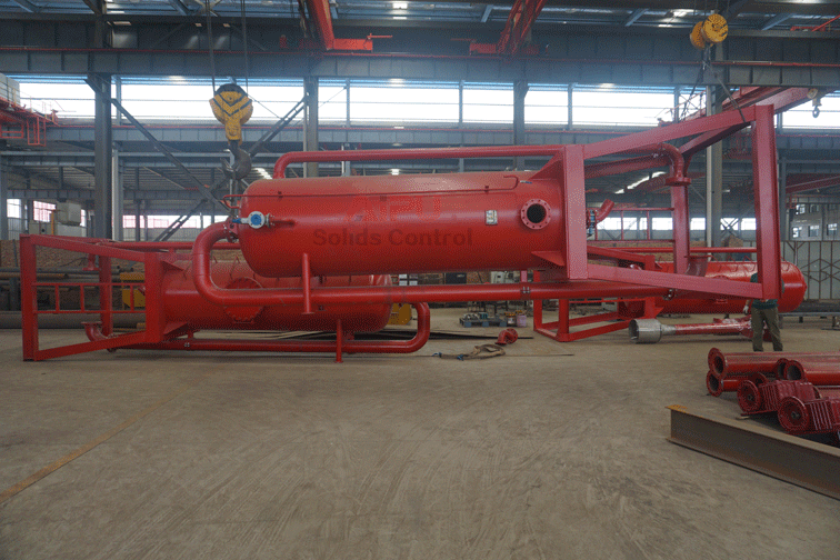
2.2 Solids-Removal Equipment: Degasser
Degassers are used to remove the gas in the mud that is to be pumped into desanders using centrifugal pumps. The efficiency of the pumps drops significantly if gas exists in the mud. Degassers are essential to the solid-removal process involving viscous mud. Shale shakers can remove a good portion of the gas from badly gas-cut mud, especially if the yield point is lower than 10 lb/100 sq ft.

A degasser is usually not necessary if the yield point of the mud is less than 6 lb/100 sq ft. If the degasser is a vacuum type (Figure-4) that requires power mud to operate the mud educator, the power mud should be taken from the degasser discharge compartment only. Violation of this rule will cause bypassing of the desander or desilter when the degasser is in operation. Conventional gas-liquid separators (Figure 5) are also used in mud drilling.
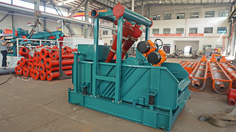
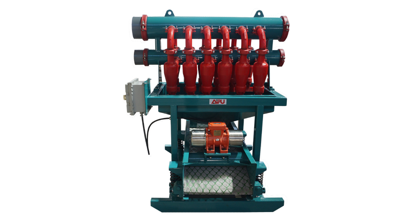
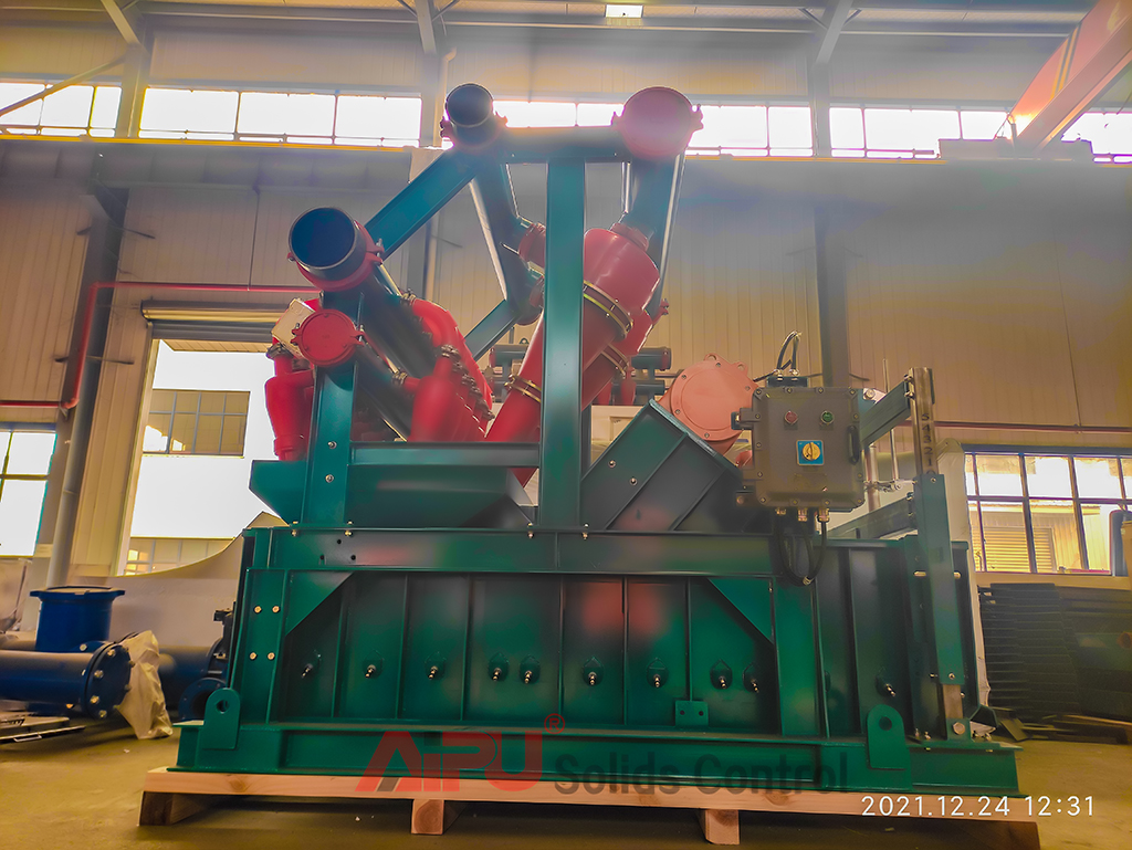
2.3 Solids-Removal Equipment: Desander, Desilter, and Mud cleaner
Desanders (Figure-6), desilters (Figure-7), and the combination of them, called mud cleaners (Figure-8), are hydrocyclone-type equipment. If operated properly, hydrocyclones can perform the finest cut of any primary separation equipment operating on the full-flow circulating rate of an unweighted mud system.
Understanding the most common designs of the hydro-cyclone is essential to proper operation. The hydro-cyclone (Figure 9) has a conical-shaped portion in which most of the settling takes place and a cylindrical feed chamber at the large end of the conical section. At the apex of the conical section is the underflow opening for the solids’ discharge. In operation, the underflow opening is usually at the bottom.
Near the top end of the feed chamber, the inlet nozzle enters tangentially to the inside circumference and on a plane perpendicular to the top-to-bottom central axis of the hydro-cyclone. The hydro-cyclone obtains its centrifugal field from the tangential velocity of the slurry entering the feed chamber.
An axial velocity component is created by the axial thrust of the feed stream leaving the blind annular space of the feed chamber. The result is a downward-spiraling velocity labeled S in Figure 9, in which T and A represent the tangential and the axial velocity components, respectively. A hollow cylinder, called the vortex finder, extends axially from the top into the barrel of the hydrocyclone past the inlet. The inside of the vortex finder forms the overflow outlet for the liquid discharge or effluent. The overflow opening is much larger than the under-flow opening. The nominal size of a hydrocyclone is the largest inside diameter of the conical portion. All dimensions are critical to the operation of any specific design and size.


