

Hydrocyclones are arranged with the unit of larger cone size upstream of the smaller unit. A separate tank is needed for each size unit. Generally, a desander and a desilter manifold are available as part of the rig equipment. Hydrocyclones should process all drilling fluid entering their suction compartments independently of the drilling-fluid circulation rate.
Suction is taken from the tank immediately upstream of the discharge tank. The number of cones in use should process at least 100% but preferably greater than 100% of the flow rate of all fluids entering the suction tank for the hydrocyclone. A backflow between the hydrocyclone discharge and suction compartments of at least 100 gpm usually ensures adequate processing. Estimations based on rig circulation rates are usually inadequate if the plumbing is not arranged properly. For example, if a 500-gpm hydrocyclone overflow is returned to the suction compartment and a 400-gpm rig flow rate enters the suction compartment, adequate processing is not achieved even though more fluid is processed than is pumped downhole. In this case, the flow entering the hydrocyclone suction compartment is 900 gpm. The fraction of drilling fluid processed would be 500/900 gpm, or 56%. For proper desanding or desilting setup see Figure 1.


R = circulating rate
D = desanding or desilting rate
E = equalizer flow rate
T = total flow into suction tank
Percent desanded or desilted
D⁄T× (100%) = percent processed
1500⁄1500× (100%) = 100%
Desanders
Desanding units are designed to separate drilled solids in the 50- to 80-micron range and barite in the 30- to 50-micron range. Desanders should be used in unweighted mud when shakers are unable to have API 140 screens (100 microns) or finer installed. They are used primarily to remove high solids volume associated with fast drilling of large-diameter top holes. In water-base drilling fluids, desanders make a median separation cut of 2.6–specific gravity (SG) solids in the 50- to 80-micron size range. The desander removes sand-size and larger particles that pass through the shale shaker screens.
Desanders are installed immediately downstream of the shaker and degasser. Suction is taken from the immediate upstream tank, usually the degasser discharge tank. Discharge from the desander is made into the tank immediately downstream. Suction and discharge tanks are equalized through valves or an opening located on the bottom of each tank.
Desanders are used continuously during drilling surface holes. Plumbing can be arranged to process all total surface pit volume after beginning a trip.
Use of desanders is generally discontinued after barite and/or expensive polymers are added to the drilling mud, because a desander discards such a high proportion of these materials. Use of desanders is generally not cost-effective with an oil-base drilling fluid because the larger cones discharge a significant amount of the liquid phase.

Desilters
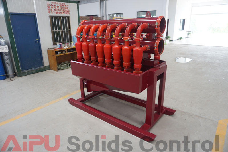
Desilter cones are manufactured in a variety of dimensions, ranging from 2 to 6 inches, and make separations of drilled solids in the 12- to 40-micron range. They will also separate barite particles in the 8- to 25-micron range. Desilters are installed downstream from the shale shaker, sand trap, degasser, and desander.
Desilter cones differ from desander cones only in dimensions and operate on exactly the same principles. Common desilter cone sizes are between 2 and 5 inches. A centrifugal pump should be dedicated to provide fluid to the desilter manifold only. Setting up a centrifuge pump to run multiple pieces of equipment is not a good idea, as doing so requires compromises in performance and opportunities for incorrect operation.
These units make the finest particle-size separations of any full-flow solids-control equipment—down to 12 microns of drilled solid. The desilter, therefore, is an important device for reducing average particle size and reducing drilled solids.
Desilter suction is also taken from the immediate upstream tank, usually the desander discharge tank. Desilter suction and discharge tanks are, again, equalized through a valve, or valves, or an opening located on the bottom of each tank. The size of the valve or opening should be:
Diameter (inches) =√ max gpm⁄15
The maximum (max) gpm will be the maximum flow rate expected, not the backflow, as there will be times when the unit will not be operating and the total rig flow rate will have to pass through the valve or opening. Suction should not be taken from the tank into which chemicals and other materials (barite and bentonite) are added because valuable treating materials may be lost.
Comparative Operation of Desanders and Desilters
The role of desanders is to reduce loading downstream on desilters. Installing a desander ahead of the desilter relieves a significant amount of solids loading on the desilter and improves desilter efficiency. High rates of penetration, especially in the unconsolidated surface hole, where the largest-diameter bits are used, results in generating larger concentrations of drilled solids. This may place desilters in rope discharge. For this reason, desanders, which have the greater volumetric capacity and can make separations of coarser drilled solids, are placed upstream of desilters. Desanders remove a higher mass (i.e., coarser drilled solids) during periods of high solids loading. Desilters can then efficiently process the reduced solids-content overflow of the desanders.
If the drill rate is slow, generating only a few hundred pounds per hour of drilled solids, the desander may be turned off and the desilter used to process the entire circulating system.
Desilters should be used on all unweighted, water-base mud. These units are not used on weighted muds because they discard an appreciable amount of barite. Most barite particles fall within the silt-size range. Desilter operation is important for all unweighted fluids; however, in oil-base muds with high viscosity (as found in deepwater drilling), the apex discharge may be centrifuged for oil-phase salvage.
Hydrocyclone Feed Header Problems
Never make a horizontal bend into an inline hydrocyclone manifold. Centrifugal force will force solids to the outside of the bend, which can overload some cones and cause solids to bypass others. It is a good idea to have a straight pipe in front of the first cone that is three times the pipe diameter. This allows time for the solids and liquid to remix evenly
(Figure 2).


One Reply to “Desanders, Desilters And Hydrocyclones Arrangements”
Comments are closed.