


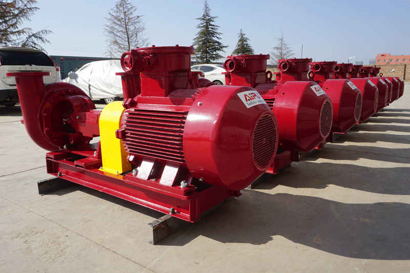
Centrifugal pumps are one of the most common types used in industry. It’s a device that pumps mud for solids control equipment. Figure 1 shows a generic, single stage centrifugal pump and Figure 2 illustrates a multistage centrifugal pump.


These pumps can utilize either open or closed impellers and may have single or multiple stage designs. Centrifugal pumps utilize Bernoulli’s principle to develop pressure (see Bernoulli’s Principle Explained below) by first increasing the fluid velocity inside an impeller and then decreasing the fluid velocity in the discharge nozzle. These pumps consist of a shaft with bearings for support and an impeller as well as a pump casing. To prevent leakage from the pump casing to the atmosphere, most pumps employ packing, single or dual mechanical shaft seals.
Centrifugal pump performance is typically presented graphically with a series of curves similar to the group shown in Figure 3. The manufacturer usually provides curves that describe how flow, differential head, net positive head required, and efficiency change with pump flow.

Useful centrifugal pump facts:
A. The suction or inlet nozzle to the pump is always bigger than the discharge nozzle.
B. If a centrifugal pump has more than one impeller inside of it is called a multistage pump. If it has, for example five impellers in it, then it is a five stage pump
Series and Parallel Operation
Centrifugal pumps may be operated in a series or parallel (see Figure 1.4) configuration. When operating pumps in series, the pressure is increased across each pump, but the flow through each pump is identical (minus any minor flow losses due to leakage). When operating in parallel, the pressure rise on each pump is identical, but the total flow is increased. However, the overall flow is not doubled with two pumps operating in parallel because of “system head” or pressure.

The easiest way to understand system head is to remember that the discharge pipe size stays the same diameter and therefore tends to restrict the higher flow generated by two pumps operating in parallel. This bottleneck effect means that two pumps operating in parallel will always deliver less than twice the flow that one pump can deliver.
There are three physical forms of a fluid energy: Elevation energy, pressure energy, and velocity energy. The higher a liquid is stored, like water in a water tower, the greater its potential energy. The greater a fluid stream’s pressure, the greater it’s potential to do work. Similarly, the greater the velocity of a stream of fluid, the higher its capability to do work. As a fluid flows down a pipe, ditch, or river, there is a constant interaction between these three forms of energy.
The interplay of the three forms of fluid energy in a flowing stream is governed by Bernoulli’s principle. Originally formulated in 1738 by the Swiss mathematician and physicist Daniel Bernoulli, it states that the total energy in a steadily flowing fluid system is a constant along the flow path. An increase in the fluid’s speed must therefore be matched by a decrease in its pressure, i.e., energy is always conserved in a fluid stream.
- This principle explains why a moving stream of liquid or gas exerts less pressure than if it were at rest. Bernoulli’s Equation can be used to approximate flow parameters in water, air, or any fluid stream that has very low viscosity as long as the fluid is assumed to have these qualities: fluid flows smoothly fluid flows without any swirls (which are called “eddies”) fluid flows everywhere through the pipe (which means there is no “flow separation”) fluid has the same density everywhere (it is “incompressible” like water).
In basic terms, the Bernoulli principle states that:
- At a constant velocity, if the elevation of a fluid stream increases, the pressure in the stream will decrease.
- At a constant velocity, if the elevation of a fluid stream decreases, the pressure in the stream will increase.
- At a constant elevation, if the velocity of a fluid stream increases, the pressure in the stream will decrease.
- At a constant elevation, if the velocity of a fluid stream decreases, the pressure in the stream will increase.
The last rule is the reason centrifugal pumps and centrifugal compressors are able to convert a high velocity flow from a rotating impeller into high pressure.
We can use the example of how an airplane wing works to better understand Bernoulli’s principle. Because of the wing’s shape, air moving over the top of the wing must travel farther and therefore faster than the air traveling across the bottom of the wing. This difference in air velocities results in a lower pressure across the top of the wing than under the wing, resulting in a net upward force that can lift an airplane. An easy way to remember Bernoulli’s principle is as follows: If the fluid’s velocity increases the pressure decreases; and if the fluid’s velocity decreases the pressure increases. These two relationships are inversely proportional. (Figure 5).

and high pressure in a wide portion of the venturi. As the velocity increases in the narrow portion, the pressure drops. As the velocity
decreases in a wider portion the pressure again increases.
Troubleshooting Centrifugal Pumps
Here are some useful relationships to remember when dealing with centrifugal pumps:
- If the pressure on the discharge pressure gauge is increasing, the flow is likely decreasing.
- If the flow is increasing, the horsepower required by the pump is increasing, which should be reflected by increasing amps or kilowatts.
- If the fluid viscosity is increasing or getting thicker, the discharge pressure will fall and the horsepower required by the pump will increase.
- If the flow is increasing, the net positive suction head required (NPSHR) will need to increase to prevent cavitation (see definition below).
Cavitation is a serious operating condition that sounds like gravel is passing through a pump. This unique “gravelly” sound associated with cavitation is due to the fact that vapor cavities or bubbles are continually forming and then collapsing in the pump’s inlet. If cavitation is not addressed and corrected quickly, the internal components of a centrifugal or positive displacement pump may be seriously damaged.
Cavitation is caused by either 1) operating a pump too close to the boiling point of the liquid at its suction or 2) by trying to pump more than a pump is designed to handle. Pump designers use a term called net positive suction head (NPSH) to determine whether there is enough suction pressure to prevent cavitation. Typical net positive suction head requirements can be seen in Figure 1.3 (Centrifugal Pump Curves), where they are depicted as dotted vertical lines, labeled: 2′, 2.5′, 3′, 3.5′, 4′, 4.5′. 2′ means that at this particular flow, two feet of liquid suction head is required to prevent cavitation, 2.5′ means that at this particular flow, two and a half feet of liquid suction head is required to prevent cavitation, and so forth.
As an operator, you simply need to remember that the higher the flow rate out of a pump the greater the suction pressure must be to insure that cavitation does not take place. An operator is in the position to control some parameters that will affect NPSHA. For example, if the pump is taking suction from a tower or tank, either the liquid level or the pressure can be increased as a means of stopping or reducing pump cavitation. Reducing the pump flow can have a positive effect on the NPSHA as well and may stop cavitation.
Related centrifugal pump troubleshooting article
Responding to Pump Problems
When you detect a pump problem and decide to act, always list the symptom or symptoms that were noted on the work request, such as not enough pressure or flow, a seal is leaking, the drive motor is tripping off line, there is high vibration on the pump, etc. Do not list what should be done about the suspected problem on the work request. Comments such as: fix the pump, change the pump, replace the pump, etc. are not helpful to the maintenance planner. Comments such as: Seized, vibrating, low pressure, tripping offline, etc. are helpful. Always, allow the maintenance crew to investigate the situation and perform what they think are the necessary corrections, adjustments or repairs.
Problems that overhauling equipment will not solve:
- Plugged suction strainers.
- Plugged discharge strainers.
- Air leaking into a suction flange.
- Check valve on standby pump leaking.
- Pump turning backward.
- Wrong pump speed.
- Bypass valve requiring too much flow.
- Blockage downstream of the pump.
- Too much flow required from the pump.
- All of these should be checked before writing a work request for repair.


