

A centrifugal pump curve comprises a grid depicting head and flow rate and a series of lines that illustrate pump performance characteristics. Figure 1. is a typical pump curve, and each set of lines will be reviewed individually.


Figure 1. is a curve for a Magnum pump, size 8 (suction)×6 (discharge)×14 (maximum impeller size) inches, operating at 1750 rpm. (Note: The suction will always be equal to or greater than the pump discharge size.) Impeller sizes, from 10 to 14 inches in diameter, can pass a spherical solid up to 1-3⁄8 inches in diameter. All this information is located above the grid. Performance characteristics of this pump will change if the speed is altered, and this curve simply shows performance when the pump is driven at 1750 rpm.


Figure 1. utilizes a left and bottom axis. Other curves may include a top and right axis. The left axis denotes the scale for TDH. This is the amount of head, in feet; the pump will produce in excess of suction head. The bottom axis denotes the scale for capacity, in U.S. gpm. In order to read a curve, review each set of lines individually. In Figure 2, several points have been marked on a line, which all depict a flow rate of 1500 gpm. If a flow rate of 1200 gpm were desired, it would be necessary to estimate the position on the grid.


Figure 3 shows several points marked on the line that all depict a TDH of 100 feet. If the pump had an inlet suction head of 20 feet and were sized to produce 100 feet of head, then the pump discharge head (total discharge head) would be equal to 120 feet. If TDH were 100 feet and fluid had to be lifted 5 feet above the suction liquid level, the total discharge head would be 95 feet.
Suppose that 8-inch-diameter SCH 40 new pipe will be used and that it lies on level ground. Table 18.12 shows that at 1500 gpm, friction loss per 100 feet of pipe will be 3.37 feet. Pipe 3000 feet long will have 30 times (3000/100) as much friction loss, or 101 feet:
(30)(3:37) = 101.
Therefore, 8-inch pipe 3000 feet long will require 101 feet of head to flow 1500 gpm.
A curve can be marked at 1500 gpm at 101 feet of head as shown in Figure 4.


Other lines on the grid represent pump performance characteristics (Figure 5).

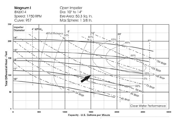
The solid curved lines in Figure 5 that extend from the left axis to the right and are labeled 10″, 11″, 12″, etc., designate the diameter of the impeller, the TDH produced by the impeller at this speed, and the flow rate produced by the impeller. The pump discharge head can be altered by changing rpm or by changing impeller diameter. If a fixed-speed driver is utilized, such as 1750 rpm, the only way to vary pump head is to alter the impeller diameter. If the requirement is for 1500 gpm at 101 feet of head and the operating speed is 1750 rpm, the impeller would have to be trimmed to 11¼ inches. Impellers can be sized to 1⁄8-inch increments,but for common installations a ¼-inch increment is sufficient.
The dash-dot curves in Figure 5 running diagonally from upper left to lower right labeled 30, 40, 50 BHP (brake horsepower), etc., designate hp required to transfer clear water. In this example, the pump requires 60 hp for clear water. This value must be corrected for fluids with an SG other than 1.0 (this will be discussed later). Solid curves running from top to bottom in a circular pattern and labeled 40, 50, 60%, etc., designate the pump efficiency. The higher the efficiency level, the lower the power operating cost. Concentric casing pumps have lower efficiency levels than other styles of pump; however, concentric-style pumps last longer and have less downtime and maintenance operating costs when transferring abrasive fluids. In the preceding example, the centrifugal pump is approximately 61% efficient. Dashed lines running from top to bottom designate minimum NPSHR for the pump to operate properly. This is explained in the next section. In this example, the pump has an NPSHR of approximately 11–12 feet.

2 Replies to “READING CENTRIFUGAL PUMP CURVES”
Comments are closed.