

Centrifugal pumps are definitely one of the most common machines in the industrial landscape. Centrifugal pump can be used as feed pump,
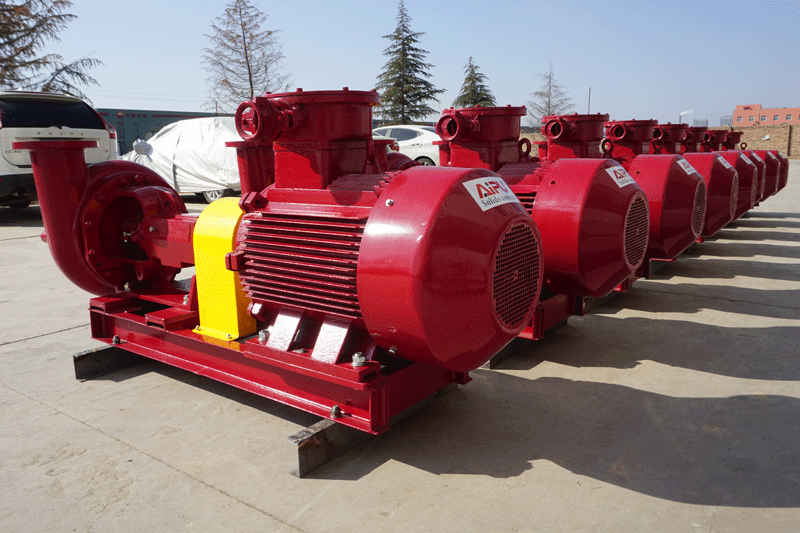
A type of pump commonly used in the handling and mixing of oilfield fluids.
Centrifugal Pump Basics
It’s safe to say that the line’s share of energy usage in the world goes towards pumping fluids with centrifugal pumps. So if you’re an industrial maintenance technician, machinist. You’ll come across these machines at some point in your career. So it will do you some good to know how they work in the first place.


In general, oilfield centrifugal pump is a machine which converts mechanical energy into the kinetic energy of oilfield centrifugal pumped fluid for the purpose of transporting that fluid from one point to another.
But in order to be classified as a centrifugal pump, oilfield centrifugal pump needs to have two unique components: the first is a rotating disc with curved blade like vanes on it called an impeller, and the second is a specially shaped pipe called a volute casing which contains the impeller and the pumped fluid.
In the most basic sense, here’s how a centrifugal pump works fluid enters the pump at the center of the impeller called the suction I. Friction between the fluid and the surface of the rotating impeller causes the fluid to rotate. Think about it like this just like the friction between the road and the rubber in your tires propels your car. Forward the impeller gains traction on the drilling fluid as it spins in contact with it.
The rotating drilling fluid is thrown to the outside of the impeller by centrifugal force. A phenomenon which causes object to revolving around a center point to move away from the center. This is how the drilling fluid picks up kinetic energy from the impeller, and this method of energy transfer by centrifugal force is why these pumps are called centrifugal pumps.
The amount of energy actually added to the drilling fluid is dependent on three factors:
- Density of the drilling fluid
- Impellers speed of rotation
- Impellers diameter


The Impeller
From the impeller, the drilling fluid is released into the chamber of the volute casing and directed around to the discharged outlet, and ultimately into the system. The most of common misconception is that these curved vanes help to move fluid by cupping it and pushing it through the pump. So then the correct direction of rotation for this impeller would be clockwise.
That’s not really what the vanes are there for. The vanes purpose is to conduct the drilling fluid along the smoothest possible path as it travels through the pump. Backwards curved vanes help to stabilize flow conditions at high speeds and reduce demands on the motor.
The correct direction of rotation for this impeller is actually counterclockwise, and you can always tell the correct direction of rotation of an impeller just by looking at the way that the vanes are curved.
The way that centrifugal pumps impart energy to drilling fluid. The impeller must always be fully submerged and in direct contact with the pumped drilling fluid. It will not suck drilling fluid through piping like a straw. Before the pump is turned on. The casing must be flooded with drilling fluid.
A process known as priming. During operation, there must be a sufficient amount of available fluid under positive pressure at the suction inlet of the pump to replace the drilling fluid which is being discharged.
This is usually accomplished by placing the pump below the fluid of the source tank. If the pump has ever starved of drilling fluid. Certainly the pumps performance will be affected. But it’s actually more serious than that.
It’s possible that the pressure at the suction eye of the impeller will drop below the vapor pressure of the pumped drilling fluid. If that happens then the drilling fluid will effectively boil. Little bubbles will form travel partway through the impeller and then collapse. It’s supersonic speeds like little blips taking bits of the impeller along with it. This is a condition known as cavitation and oilfield centrifugal pump that’s experiencing cavitation is not long for this world.
The Volute Casing
Volute refers to the shape of the casing. A volute is a geometric shape defined as a spiral with an ever increasing radius like a snail shell. Hopefully you’ll notice that the volute chamber on this pump doesn’t stay the same size all the way around it. Actually increases an area closer to the discharge outlet. At the point where the discharge outlet begins and the volute chamber sort of starts over.
There’s a wedge like protrusion called the cut water. The cut water physically separates the discharge outlet The volute chamber. It ensures that drilling fluid actually leaves the pump instead of just recirculating over and over again inside of the volute chamber now the increasing area of the volute chamber is essential to the function of the pump. Because that’s how the pump develops.


Centrifugal Pump Pressure
Oilfield centrifugal pump also needs to be able to develop sufficient pressure to meet the requirements of the system. Usually this involves overcoming gravity by raising drilling fluid from a lower elevation to a higher elevation, and overcoming the resistance or friction of the pipes which conduct the drilling fluid.
Think of pressure is the ability to accomplish a task and flow speed as how quickly the task can be accomplished. To build pressure, the pump has to do some science magic to convert kinetic energy into pressure energy. As drilling fluid travels through the volute chamber, it actually starts to slow down as the area of the volute chamber increases.
That’s because flow rate or the amount of drilling fluid which is moved during a given length of time is dependent on two factors: one is the speed of the drilling fluid and the other is the size of the chamber through which it’s moving. Meaning how much of the drilling fluid is moving at that speed.
If the flow rate is constant then an increase in the size of the chamber would result in a corresponding decrease in the speed of the drilling fluid. This is where a guy by the name of Daniel Bernoulli comes in he discovered 300 years ago. That there’s an inverse relationship between a drilling fluids velocity or speed, and it’s pressure meaning that if the velocity goes up, then the pressure comes down.
If the velocity goes down then the pressure automatically goes up. As the drilling fluid is slowing down in the ever expanding volute chamber. It’s also picking up pressure. By the time the drilling fluid reaches the discharge outlet. A great deal of its kinetic energy has been transformed into pressure energy.
