

Most drilling rigs are equipped with at least one shale shaker. The purpose of a shale shaker, as with all drilled-solids removal equipment, is to reduce drilling cost. Most drilling conditions require limiting the quantity and size of drilled solids in the drilling fluid.
Shale shakers remove the largest drilled solids that reach the surface. These solids are the ones that can create many well-bore problems if they remain in the drilling fluid.
WARNING: Electrical Hazard—follow ALL national electric codes, local electric codes, and manufacturer’s safety and installation instructions. Always conform to regulatory codes, as apply regionally and internationally
1. Selection of Shaker Screens
Some proprietary computer programs are available that reportedly allow predictions of screen sizes used on some shale shakers. Most of these computer programs have been verified with data taken from laboratory-prepared drilling fluid with limited property variation. Different drilling-fluid ingredients can reduce the capacity of a shaker system.
For example, a drilling fluid containing starch is difficult to screen because starch, acting as a good filtration control additive, tends to plug small openings in screens. Drilling fluids with high gel strengths are also difficult to screen through fine screens.
No charts will be presented here that purport to predict screen sizes that will handle certain flow rates. Screen selection for various shale shakers is primarily a trial-and-error evaluation. The best advice is to contact the manufacturer for recommendations for various geographical areas.
2. Cost of Removing Drilled Solids
Few wells can be drilled without removing drilled solids. However, even for 3000- to 4000-ft wells, one problem created by drilled solids, such as lost circulation, stuck pipe, or a well-control problem, will more than nullify the modest savings resulting from the decision not to properly process the drilling fluid. In expensive operations, the proper use of solids-removal equipment will significantly reduce drilling costs.
Although drilled solids can be maintained by simply diluting the drilling fluid to control the acceptable level or concentration of drilled solids, the expense and impracticality of this approach are evident using the following example. A 12(1/4)-inch-diameter hole 1000 feet deep will contain about 144 barrels of solids. If these solids are to be reduced to a 6% volume target concentration, they must be blended into a 2400-barrel slurry. To create the 2400 barrels, the 144 barrels of drilled solids must be added to 2256 barrels of clean drilling fluid: (144 bb/2256 + 144 bbl)= 6% volume.
Not only would the cost of the clean drilling fluid be prohibitive, but most drilling rigs do not have the surface volume to build 2256 barrels of clean drilling fluid for every 1000 feet of hole drilled. (See Chapter 15 for a complete discussion of dilution calculations.)
Remove as many drilled solids as possible with the shale shaker. Shakers are a very important component of this process, but they are still only one component of a complete drilled-solids removal system. All of the system must be operated with careful attention to details to develop the most efficient drilled-solids removal. Complete processing will decrease the cost of building excess drilling fluid. Proper drilledsolids control is directed primarily at reducing the cost of drilling.
3. Specific Factors
Some specific factors that should be considered when designing the shale shaker system are flow rate, fluid type, rig space, configuration/power, elevation available, discharge dryness (restrictions).
Most programs extrapolate laboratory-generated performance curves to predict field performance. Unfortunately, laboratory-manufactured drilling fluid does not duplicate properties of a drilling fluid that has been used in a well. High shear rates through drill-bit nozzles at elevated temperatures produce colloidal-size particles that are not duplicated in surface-processed drilling fluid.
Flow Rate
The flow rate that a particular shaker/screen combination can handle depends greatly on the flow properties of the drilling fluid. The lower the values of PV, YP, gel strength, and mud weight, the finer the screen opening sizes that can be used on a shale shaker. The conductance of the shaker screen provides a guide for the fluid capacity but does not reveal how the screen will actually perform. Screens with the same conductance may not be able to handle the same flow rate if used on different shale shakers.
Shaker screen selection programs have been developed by several companies to predict the quantity of solids that can be removed from a drilling fluid by various shaker screens on specific commercial shakers. Most programs start by assuming that the flow rate of drilled solids reaching the surface is identical to the generation rate of the drilled solids. Unfortunately, many drilled solids are stored in the well bore and do not reach the surface in the order in which they are drilled. Frequently, in long intervals of open hole, as many drilled solids enter the drilling fluid from the sides of the well bore as are generated by a drill bit.
One proposed relationship shows that the maximum flow rate (Q) that can be handled by a shaker is inversely proportional to the product of the PV and mud weight and proportional to the screen conductance (K). This relationship would answer the question, If a linear motion shale shaker is handling 1250 gpm of a 10.3-ppg drilling fluid with a PV of 10 cP on a 120 square MG mesh screen, what flow rate could be handled on a 200 square MG mesh screen if the mud weight were increased to 14.0 ppg and the PV becomes 26 cP
Q2=[(K2)(PV1)(MW1)/(K1Þ)(V)(MW2)]*Q1
Q2=[(1.24 kd/mm)(10 cP)(10.3 ppg)/(0.68 kd/mm)(26 cp)(14.0 ppg)]*1250 gpm
OR
Q2=645GPM
The problem with this equation is that it fails to account for other rheological variables. For example, if the gel strength of the 10.3-ppgdrilling fluid were increased significantly, the shaker could no longer handle the fluid.
Some shakers might handle 750 gpm of an 11.0-ppg drilling fluid with a certain PV. If PHPA or a high concentration of starch is added to this fluid, the shaker capacity might be only 350 gpm.
In both cases, the PV would change very little but would have a significant effect on the screening capability. If there are no other property changes in a drilling fluid except mud weight and PV, the preceding equation can help predict what flow rate can be handled.
Rig Configuration
On some drilling rigs, the derrick rig floor is not high enough to allow some shale shakers to be used because the flow line is not high enough. Small land rigs frequently have difficulty positioning larger shale shakers so that the flowline has sufficient slope to prevent fluid from overflowing the bell nipple.
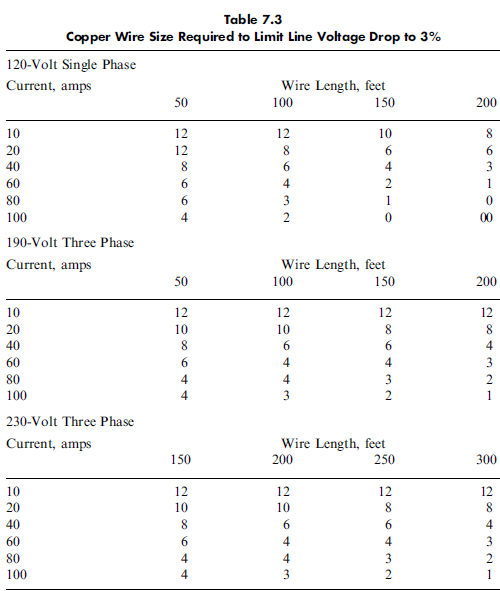
Whichever shaker or shakers are used, consideration must be given to providing sufficient safe power to the shaker motors. Check with the manufacturer about electrical service needed for the
shaker used.
Discharge Dryness
In some areas, drilled solids and drilling fluid cannot be discarded at the rig location. This applies to both land and offshore rigs. In some areas, the cost of handling discarded material may require drying the discard. The fine screens discharge much wetter solids than do very coarse screens. Hence, fine-screen discharge may require additional processing with dryers or dewatering techniques.
