

An important problem in the oil industry is the treatment of produced water, especially in the case of offshore oil production where space and floor area, needed for the separation equipment, are extremely costly. Increased production of water occurs when an oil field matures, and the availability of efficient and cost-effective techniques partly determines the period during which economic production is possible. For the final de-oiling process several techniques are available, of which plate separation, centrifugation and the use of hydrocyclones are important ones. Common characteristics of these three techniques are that only insoluble oil components can be removed, and that the prevailing separation process is movement of the oil droplets with respect to the continuous phase, water, as a result of an external force, viz. the gravity force or the centrifugal force.
The three mentioned techniques are the subject of this paper: they are described and analyzed, and typical data on e.g. volume, flow-rate and performance are given. Next the results of some laboratory experiments on plate separation and centrifugation are presented. Subsequently the three techniques are compared, and possibilities for performance enhancement are discussed. We will start, however, with some remarks on other separation techniques.
Other De-Oiling Techniques
Plate separation, centrifugation and the use of hydrocyclones are not the only techniques that are – or can be – used for de-oiling of produced water. Others are:
- Biological degradation. This technique has two disadvantages in connection with use in the oil industry, viz. the relatively large amount of space needed for a separator unit and the relatively large amount of time needed for the breakdown of the oil products.
- Removal of oil by membrane filtration has been practiced in the past. There are, however, maintenance problems and, more important, only relatively small produced water flow-rates can be handled.
- This technique has been, and still is, frequently used for the de-oiling of produced water. The key difficulty of this technique is the creation of favorable circumstances for separation, and in this respect there are few similarities between, on the one hand, a flotation unit and, on the other hand, a plate separator, centrifuge or hydrocyclone.
- This technique is used for the removal of soluble oil components. The occurring phenomena differ considerably from the ones taking place in a plate separator, centrifuge or hydrocyclone.
Of the mentioned other de-oiling techniques two, viz. biological degradation and filtration, seem to have too many drawbacks for their effective use in the oil industry, and therefore become uninteresting. The other two, flotation and stripping, are and will remain important separation tools.
The Plate Separator
In the channel of a plate separator (see Fig. 1), oil droplets flow from the inlet to the outlet with the same horizontal velocity as the continuous phase, water. Due to the density difference with water, they also have a vertical velocity. An oil droplet is separated when, as a result of its vertical velocity, it reaches the top of the channel and coalesces with the other separated droplets. The stationary vertical velocity can be found by equating the buoyancy force acting on a droplet and the resistance-to-flow force as defined in Stokes’ law
Following Notes of The Present Equation. (Plate Separator)
- Separator angle. In case the angle of the separator with the horizontal is instead of zero, a droplet has to travel a larger distance to reach the upper side of the separator channel.
- Reynolds number. Separation is only achieved in case the flow in the separator channel is laminar. In practice separator channel heights of about 3-20 mm are encountered. For the linear velocities this implies that the largest velocities which can be permitted are some tens of cm/s.
- Velocity profile. The relation for the critical oil-droplet diameter was derived under the assumption of a constant , (plug flow), while” iii practice the velocity- profile in the channel is parabolic. It can be shown that the derived equations are also valid in case the velocity profile is parabolic.
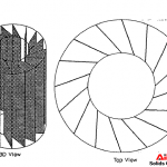
- Separator-channel shape. To improve the removal of the separated oil, the separator plates (and, consequently, the separator channels) of commercial separators are often corrugated, see Fig. 2. Also for a corrugated channel the presented equations remain applicable. It is noted, however, that the maximum allowable Reynolds number will be somewhat lower than for flow in a straight channel.
To be able to compare a plate separator with a centrifuge and a hydrocyclone, we assume the following typical data: length, width and height 2.00 m; channel height 5.0 mm; plate thickness 1.0 mm; angle with the horizontal. Furthermore we assume mat the maximum Reynolds number is 1000. Using 1000 kg/m3, 100 kg/m3, 0.0010 Pas and 10 m/s2 for, respectively, the density of water, the density difference between water and oil, the dynamic viscosity of water and the acceleration of gravity, we find a maximum v of 10.0 cm/s. This yields, at the maximum flow-rate of 0.333 m3/s, a critical oil-droplet diameter of 67 μm. This DC-value is unattractively high, and in practice one would use a lower flow-rate so that a lower DC can be achieved: e.g. D;s of 30, 35 and 40μm correspond with flow-rates of, respectively, 0.067, 0.091 and 0.119 m3/s. In practice the lower limit of the critical oil droplet diameter is believed to be in the 20-30 μm range,
The Centrifuge
In Fig. 3 the principle of the disc-stack centrifuge as manufactured by Al fa-Laval is sketched. The separation section consists of a stack of conical discs, with the distance between the discs typically being of the order of 1 mm. Separation only takes place in the outer section, where the centrifugal force is largest. An alternative design for separation was developed by Plat by replacing the disc stack by a set of vertical plates. Fig. 4 depicts the general idea, while Fig. 5 gives the four types of channels which were investigated.
Also for the centrifuge we make some assumptions for the typical dimensions: location of the separation section between 5.0 and 7.0 cm from the rotation axis; height of the separation section 25 cm; distance between the separator plates/discs 1.0 mm; angle 1345°; rotation velocity 6000 rev./min. For the water density, density difference between oil and water and the viscosity of water we take the same data as for the plate separator (see previous section). Using again a critical Reynolds number of 1000, this yields an (average) maximum water velocity of 0.50 rn/s. This corresponds with a flow-rate of 0.0236 m3/s, while the critical oil-droplet diameter in this case can be calculated as 14 pm. Also here lower DJs can be achieved by decreasing the flow-rate: e.g. DC’S of 5, 6 and 8 μm correspond with flow-rates of, respectively, 0.0031, 0.0045 and 0.0079 m3/s.
The critical oil-droplet diameter which can be achieved with a centrifuge can be even lower than 5 μm. With the configurations sketched in Fig. 5, De’s in the 2 μm range have been reached. It is believed, however, that much lower values than this cannot be realized. To this is added that very low values correspond with extremely low flow-rates, which can make such a separation procedure unattractive and unpractical.
The Hydrocyclone
In a hydrocyclone the centrifugal acceleration is the result of the enforced, tangential entrance of the produced water into the separator, see Fig. 6. The oil droplets will eventually be concentrated in the centre, the core, of the cyclone and will leave the device through the overflow. The water goes out at the underflow. The processes in a hydrocyclone are more complex’ than those occurring in a centrifuge. Firstly the acceleration and the influx flow-rate are coupled. A larger influx velocity induces larger centrifugal forces, and this means that the performance of the cyclone is influenced by this flow-rate. Secondly the local acceleration is dependent on the distance to the core centre and is also strongly influenced by the geometry of the cyclone. Thirdly the separation process is also influenced by the ratio between the overflow and influx flow-rates.

The hydrocyclone for de-oiling of water was developed in 1980 by Colman and Thew. For its performance we base ourselves on an article by Young et al., in which a hydrocyclone with a 35 mm radius, and variants thereof, was tested. Important results of this investigation were the following:
- Flow-rate. For influx flow-rates of 0.0013 up to 0.0023 m3/s, the efficiency is constant (about 90%), provided the ratio between the flow-rates of overflow and influx is larger than about 1%. The absence of the influence of flow-rate is somewhat surprising. Apparently the decrease in centrifugal acceleration for decreasing flow-rate, which has a negative effect on the efficiency, is compensated in this flow-rate range by the increase in residence time in the cyclone, which has a positive effect.
- Oil-droplet size. There is a marked influence of the oil droplet size on the separator efficiency, For D50-values of 55, 40 and 35 pm the efficiency is relatively high, but this decreases to about 70 %. and about 50 % for D50 of 25 μm and 15 μm, respectively. These figures are for relatively light oil; for heavier oil the efficiency is even lower. A possibility to increase the efficiency is operating with two hydrocyclones in series (tandem configuration).
- Other parameters. The influence of other parameters which were investigated by Young et al. were inlet oil concentration, oil-water density difference, and geometrical parameters such as overflow diameter, cone angle and feed size. A very significant effect was only measured for the density difference, of which an increase led to an increased cyclone performance.
For comparison with a plate separator and a centrifuge we list characteristic data of the Colman-Thew hydroclone: maximum inner diameter 70 mm, length more than one meter, typical flow-rate range ‘0.001-0.003m3/s and capable of removing oil droplets of about 20μm and larger.
Experiments on Plate Separation and Centrifugation
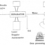
Experiments have been carried out to determine the separation efficiencies of a plate separator and a centrifuge. Fig. 7 gives the set-up for the testing of a plate separator. A similar set-up was used for a centrifuge. The tap-water flow is divided into two streams: the larger part flows in the direction of the separator, while the smaller part is forced through a needle valve, where oil is added to the water stream. Subsequently this oil-water mixture is led into the main stream. The turbulent conditions in the valve lead to dispersion of the oil. Consequently, the influx of the separator consists of an oil-in-water dispersion. The oil-droplet-size distribution of this dispersion can be varied by manipulating the following parameters: flow-rate in the bypass, pressure of the oil pump and position of the needle-valve stem. With a particle size analyzer the droplet-size distributions of influx and effluent can be measured, and from these data the separation efficiency of the separator as a function of droplet diameter can be derived.
Fig. 8 gives an example of the results for a plate separator with flat plates and a separator with corrugated plates. It can be seen that there is no significant difference between the results for flat plates and those for corrugated plates, and that these results are in good agreement with the theoretical prediction. We note that, for the laboratory experiments, configurations were used with channel heights which were larger and lengths which were shorter than one would use in practice. This explains the fairly large critical diameter of about 100 μm. Fig. 9 gives an example of results achieved with a centrifuge, for three flow-rates. Also here there is a good agreement between the experimental results and the theoretical prediction.
Comparison of Plate Separator, Centrifuge and Hydrocyclone
For the comparison between the three separators in question we will consider three characteristics: the critical droplet diameter, the flow-rate and the separator volume.
- Critical oil-droplet diameter. The separators do not have a fixed critical droplet diameter, because this parameter is influenced by e.g. oil-water density difference, separator channel dimensions and separator geometry. Furthermore is valid, for plate separator and centrifuge, that this critical diameter decreases with decreasing flow-rate, which will lead in practice to choosing the flow-rate (the separator capacity) in such a way that the resulting DC is acceptable. Nevertheless one can speak of typical DC-ranges: about 30-40 μm for the plate separator, about 5-10 pm for the centrifuge and about 20 μm for the hydrocyclone, to which is added that for all these devices lower values are achievable.
- Separator volume. Taking into account extra volume, because the total volume of a separator (or the space it is taking in) is larger to much larger than the separation section proper, the volumes of one plate separator, one centrifuge and one hydrocyclone as described earlier can be roughly estimated at about 15-20, about 0.02-0.03 and about 0.01-0.02 m3, respectively. Combination of these data with the total flow-rate ranges as given above yields for the flow-rate per unit volume 0.004-0.020, 0.10-1.00 and 0.05-0.30 s-’ for plate separator, centrifuge and hydrocyclone, respectively. Although these figures are only indicative, they show that with respect to flow-rate per unit volume the centrifuge performs better than the hydrocyclone, which in its turn is better than the plate separator.
With respect to performance on both critical oil-droplet diameter and ratio (flow-rate)/(separator volume), the ranking is centrifuge, hydrocyclone, plate separator. In practice, however, the hydrocyclone is more in use than the centrifuge. This has to do with three circumstances:
- In many cases the better performance of the centrifuge with respect to DC is unnecessary
- The centrifuge needs electrical energy (which a hydrocyclone does not need) to let it rotate with a high rotation frequency.
- The centrifuge is a (much) more expensive separation device than the hydrocyclone.
New Developments
Concerning the plate separator there are a number of possibilities to improve its performance. Decrease of the channel height leads to a decreasing Dc. There is a limit, however, to this height decrease because of the probability of channel blockage. Moreover, for a constant separator volume a channel-height decrease leads to more separator plates and, hence, to a larger plate volume and a smaller net separator volume. A point in favor of height decrease is that it allows a higher maximum velocity vx, because the maximum Reynolds which can be permitted is reached for a larger VX. Also increase of the separator-channel length leads to a decreasing DC, but it is noted that the separator volume increases proportionally, so that this does not lead to a performance enhancement in terms of flow-rate per unit volume, The last way in which a better performance can be achieved is decrease of the water viscosity. This can be realized by practicing separation at a higher temperature, but this implies heating of the produced-water stream, which can be rather costly.
For the centrifuge we have already mentioned possibilities for performance enhancement. These can be achieved by introducing novel separator internals as sketched in Fig. 5 instead of using a stack of conical discs (Fig. 3). With respect to channel height there is the possibility to realize smaller heights than are possible with discs, although also here there is a lower limit because of the probability of channel blockage for very narrow channels. The largest advantage of the novel internals, however, is the better way in which the produced water is distributed over the channel. For the conical discs the water has to flow through a separate channel consisting of holes in the discs, which leads to a non-uniform distribution: the flow-rate in the lower channels will be higher than that in the upper channels. This will have an unfavorable effect on the centrifuge performance when the height of the separation section becomes too large. A centrifuge provided with novel internals does not have this drawback, thus the separation section can be much larger. Therefore it is expected that a centrifuge provided with novel internals can perform better, and that a net separation volume can be achieved which is substantially higher than that of a disc-stack centrifuge.
A recent development concerning hydrocyclones design are work by Dirkzwager on an axial cyclone, in which the spinning motion is not caused by the tangential influx, but by an axial swirl element with vanes. The predictions on the behavior of this cyclone are based on calculations and numerical simulations. The ultimate objective is to develop a cyclone which is relatively small, has a high throughput, is efficient and has a much lower pressure drop than a conventional hydrocyclone (of which the pressure drop is typically of the order of 1-3 bar). Preliminary data about this axial cyclone are: pressure drop about 0.4 bar for a flow-rate of 0.0020 m3/s. Apart from investigating the Colman-Thew hydrocyclone, Young et al. (Ref. 7) also adapted this device, which led to an equal performance for higher flow-rates. They also designed cyclones with a lower DC, but these can only be used for relatively small flow-rates. We already mentioned the option to increase the efficiency of a cyclone by using two cyclones in a tandem configuration. Consequently, there are a number of possibilities to improve the performance of a hydrocyclone.
Apart from developments on equipment design there is also an interesting development concerning the production process, viz. separation of oil from water not at the surface but down-hole, at the bottom of the well, see Kjos et al. Because the available space in a borehole is very small, this manner of separation can only be realized with a hydrocyclone or a centrifuge. Up till now only hydrocyclones are used for this production technique. Evidently the use of centrifuges is considered uneconomical. Application of this down-hole separation technique makes it attractive to search for separation devices which are even more compact than those available now. Furthermore we remark that, apparently, efficient separation can be carried out with a hydrocyclone. This means that, at the bottom of the well, the majority of the oil droplets will be larger than about 20 μm (being the order of magnitude of the critical – oil-droplet diameter of a hydrocyclone). However, in practice also relatively small oil droplets may be present in the borehole, as is predicted by Janssen et al. Under these circumstances the use of a hydrocyclone may be ineffective, and it would be a logical step to consider the use of a centrifuge in these cases.
Conclusions
- Measured removal efficiencies of a plate separator and a centrifuge are in good agreement with theoretical predictions.
- With respect to performance in the sense of ratio (flow-rate)/( separator-volume) and critical oil-droplet diameter, the ranking of the three discussed separator types is: centrifuge, hydrocyclone, plate separator.
- Enhancement of separator performance through design alterations is possible for all three separator types.
- When the available space for separation is limited (offshore production) to very limited (down-hole separation), a plate separator will not, or cannot, be used. Because of economic reasons the chosen separator type is usually a hydrocyclone.
- There will remain a tendency to stive for more compact separators. Both for hydrocyclones and centrifuges there are possibilities in this respect.
- When very small oil droplets, e.g. in the 5 pm range, have to be removed, this can only be realized by using a centrifuge. The high costs of this separation device, however, are its main drawback.


Nomenclature
D = oil-droplet diameter
Dc= critical oil-droplet diameter
D50 = oil-droplet diameter for which is valid: 50 vol. YO of all oil droplets have a smaller diameter
g = acceleration of gravity
H= separator-channel height
L = separator-channel length
λ = distance to the rotation axis
Vx = average water velocity
v, = stationary vertical oil-droplet velocity
cz = angle between plate-separator channel and horizontal
Y = angle between centrifuge channel and rotation axis
Δp = difference between the densities of water and oil
q = removal efficiency of a separator or separator channel
P = dynamic viscosity of water
cu= angle velocity of the centrifuge
Fast reading:
Frequently oil is produced while, simultaneously, large amounts of water are produced as well. Under these circumstances it is important to have compact and efficient de-oiling equipment at one’s disposal. After some remarks on other de-oiling methods, the attention in this paper is focused on three separation techniques: plate separation, centrifugation and the use of hydrocyclones. The working principles are described and subsequently typical data on separation efficiency, geometry of the separator section, separator volume and critical oil-droplet diameter are derived or given. Analysis of these data shows that the ranking with respect to performance of the three separator types is: centrifuge, hydrocyclone, plate separator. In the last section of the paper attention is given to some recent developments concerning centrifugation and the use of hydrocyclones.

One Reply to “Comparison of Plate Separator, Centrifuge and Hydrocyclone”
Comments are closed.