

Stand pipe Manifold
The stand pipe manifold is designed with provisions for stand pipe connection to the rig pumps (1 & 2), the cement pump and the kill line. This enables the conduction of drilling mud to the bit, and cement to the annulus, during drilling and cementation, respectively. In addition, a separate line connects this manifold to a manual adjustable choke. All lines can be isolated by gate valves. Below is a diagram showing the standpipe manifold:
Line-up Procedures for Flow Systems.
Stand Pipe Manifold
- Line up and connect both pumps (1) and 2 to Stand Pipe and open all valves in between.
- Keep cement pump shut.


A detailed description of the Standpipe Manifold is as follows:
- Gate Valves: These are fully operational valves that are either fully opened, fully closed or in a cracked position.
- Manifold Pressure Gauge: This measures the Standpipe pressure.
Drawwork Console:
The Drawwork console, which looks exactly like the one on a regular drilling rig contains five clutches and rheostat controls that control the drum, rotary table and the pumps (both mud and cement). In addition, the drawwork brake enhances a mechanism for controlling the weight on bit, penetration rate and the lifting of the drill string.
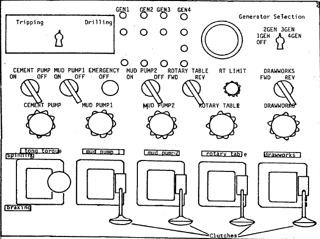

A detailed discussion of the Drawwork Console is as follows:
- Cement Pump Switch:A rotary switch that engages power to cement pump blower.
- Mud Pump 1 Switch: A rotary switch that engages power to mud pump 1.
- Mud Pump 2 Switch: A rotary switch that engages power to mud pump 2.
- Rotary Table Switch Forward/Reverse: A rotary switch that applies power to the rotary table. Note: Reverse direction is inoperative.
- Rotary Torque Limit: Rotating control that allows the student to adjust the maximum power applied to the rotary table. Note: If limit is not properly set, a twist-off will occur.
- Drawworks Forward/Reverse: A forward and reverse switch that applies power to the drawworks.
Note: Reverse switch is inoperative. - Cement Pump Rheostat: A control allowing the student to increase or decrease the cement pump speed.
- Mud Pump 1 Rheostat: A control allowing the student to increase or decrease the mud pump speed.
- Mud Pump 2 Rheostat:A control allowing the student to increase or decrease the mud pump 2 speed.
- Rotary Table Rheostat:A control allowing the student to increase or decrease the rotary table speed.
- Mud Pump 1: Clutch used in engaging or disengaging mud pump. #1
- Mud Pump 2: Clutch used in engaging or disengaging mud pump. #2
- Drawworks: Clutch used in engaging or disengaging mud pump. #1 Note: The clutch must be energized for foot operation.

My brother recommended I might like this blog. He was entirely right. This post truly made my day. You cann’t imagine simply how much time I had spent for this info! Thanks!