

Hoppers, mud guns, desanders, desilters, degassers, and triplex pumps requiring supercharging all have one thing in common: they require 76–80 feet of inlet head to operate as designed. Exceptions do exist, and the equipment manufacturer should be consulted. This simplifies the job of sizing centrifugal pumps. Since most applications in drilling systems require 80 feet of head at the inlet of the equipment, knowledge of volume needed by each piece of equipment is required. Following are standard flow rates when equipment has an 80-foot inlet head:
- 6-inch hopper with standard 2-inch nozzle: 550 gpm.
- 4-inch hopper with 1½-inch nozzle: 300 gpm.
- Mud gun with ¾-inch nozzle: 85 gpm per gun.
- Mud gun with 1-inch nozzle: 150 gpm per gun.
- Desander/desilter 4-inch cone: 60 gpm per cone.
- Desander/desilter 10-inch cone: 500 gpm per cone.
- Degasser: 600 gpm.
These are general standards. All values should be verified prior to sizing the centrifugal pump. Considering both suction and discharge conditions when sizing a centrifugal pump is very important.
Friction Loss and Elevation Considerations
Once the head requirement at the end of the transfer line and volume required is known, it is time to determine elevation and friction losses that need to be overcome. Elevation is the distance above or below the centerline of the pump. Therefore, if a centrifugal is mounted on deck 1 and the transfer line ends on deck 2, which is 20 feet above the pump centerline, then the discharge elevation is 20 feet. This 20 feet of elevation must be added to the discharge head required. Additionally, the suction supply tank elevation must be considered. If minimum liquid surface is 8 feet above the pump centerline, then 8 feet of positive head will feed the
pump and can be subtracted from the discharge head requirement. However, if the minimum liquid surface level is 8 feet below the pump centerline, a negative head is created and this must be added to the discharge head requirement.
Friction loss is the amount of resistance to flow, measured in feet of head, that occurs when fluid flows through pipe, valves, elbows, etc. This resistance varies with flow rate and pipe diameter.
Take, for example, a contractor who wishes to operate a two-cone desander equipped with 10-inch cones and anticipates the maximum mud weight to be 16 lb/gal. The pump is mounted on the same deck as the desander and is 150 feet away. The inlet to the desander is 10 feet above the deck. The supply tank minimum liquid surface level is 8 feet above the pump centerline. Remember that two 10-inch cones will flow 1000 gpm and that the desander requires 80 feet of inlet head:
80 feet required by desander + 10 feet of discharge elevation − 8 feet of positive suction elevation + ? discharge friction loss + ? suction friction losses = TDH required at discharge of centrifugal pump.
Since friction losses are unknown, refer to values taken from Table 1.(values taken from Centrifugal Pumps Velocity Measured PDF).
Table 1.
Excerpt Centrifugal Pumps Velocity Measured PDF
| Line Size Schedule–40 Steel Pipe | Velocity (ft/sec) | Head Loss (ft/100ft) |
| 4 | 25.5 | 64.8 |
| 5 | 16 | 15.8 |
| 6 | 11.1 | 6.17 |
| 8 | 6.41 | 1.56 |
| 10 | 4.07 | 0.50 |
Chart based on 1000-gpm flow rate.
At 1000 gpm, 4- and 5-inch lines have line velocities that exceed the maximums recommended and should therefore not be used. A 10-inch line has a velocity that does not meet minimum velocity requirements, and settling may occur. Line velocities for 6-inch pipe are excessive for the suction side of the pump. This means that optimum-size suction piping for this application is 8 inches. Discharge piping could use either 6-inch or 8-inch pipe, but it would be most economical to utilize 6-inch piping.
Since suction and discharge line sizes have been selected, friction losses can be calculated. In this example, assume that the discharge line is new 6-inch SCH 40 and has one butterfly valve, six ells, one running tee, and one branched tee and is 150 feet long. The suction line is new 8-inch SCH 40 and has one elbow, one branched tee, and one butterfly valve and is 30 feet long. Each fitting causes friction losses that can be measured and compared to equivalent feet of pipe Table 2.
Table 2.
Friction Loss in Pipe Fittings in Terms of Equivalent Feet of Straight Pipe
| Nominal Pipe Size | Actual Inside Diameter | Gate Valve (f.o.) | 90ºElbow | Long Radius 90º or 45º std. elbow | Std. Tee (thru flow) | Std. Tee (branch flow) | Close return Bend | Swing Check Value (f.o.) | Angle Valve (f.o.) | Glbole Valve(f.o.) | Butterfly valve |
| 1 | 1.61 | 1.07 | 4.03 | 2.15 | 2.68 | 8.05 | 6.71 | 13.4 | 20.1 | ||
| 2 | 2.067 | 1.38 | 5.17 | 2.76 | 3.45 | 10.3 | 8.61 | 17.2 | 25.8 | 7.75 | 7.75 |
| 2 | 2.469 | 1.65 | 6.17 | 3.29 | 4.12 | 12.3 | 10.3 | 20.6 | 30.9 | 9.26 | 9.26 |
| 3 | 3.068 | 2.04 | 7.67 | 4.09 | 5.11 | 15.3 | 12.8 | 25.5 | 38.4 | 11.5 | 11.5 |
| 4 | 4.026 | 2.68 | 10.1 | 5.37 | 6.71 | 20.1 | 16.8 | 33.6 | 50.3 | 15.1 | 15.1 |
| 5 | 5.047 | 3.36 | 12.6 | 6.73 | 8.41 | 25.2 | 21 | 42.1 | 63.1 | 18.9 | 18.9 |
| 6 | 6.065 | 4.04 | 15.2 | 8.09 | 10.1 | 30.3 | 25.3 | 50.5 | 75.8 | 22.7 | 22.7 |
| 8 | 7.981 | 5.32 | 20 | 10.6 | 13.3 | 39.9 | 33.3 | 58 | 99.8 | 29.9 | 29.9 |
| 10 | 10.02 | 6.68 | 25.1 | 13.4 | 16.7 | 50.1 | 41.8 | 65 | 125 | 29.2 | 29.2 |
| 12 | 11.928 | 7.96 | 29.8 | 15.9 | 19.9 | 59.7 | 49.7 | 72 | 149 | 34.8 | 34.8 |
| 14 | 13.124 | 8.75 | 32.8 | 17.5 | 21.8 | 65.6 | 54.7 | 90 | 164 | 38.3 | 38.3 |
| 16 | 15 | 10 | 37.5 | 20 | 25 | 75 | 62.5 | 101 | 188 | 31.3 | 31.3 |
| 18 | 16.876 | 16.9 | 42.2 | 22.5 | 28.1 | 84.4 | 70.3 | 120 | 210 | 35.2 | 35.2 |
| 20 | 18.814 | 12.5 | 47 | 25.1 | 31.4 | 94.1 | 78.4 | 132 | 235 | 39.2 | 39.2 |
Discharge line:
- (1) 6-inch butterfly valve = 22.7 feet.
- (6) 6-inch ells = 91.2 feet.
- (1) 6-inch running tee = 10.1 feet.
- (1) 6-inch branched tee = 30.3 feet.
Actual feet of pipe = 150 feet. Total = 304.3 equivalent feet of 6-inch pipe. Suction line:
- (1) 8-inch ells = 20 feet.
- (1) 8-inch branched tee = 39.9 feet.
- (1) 8-inch butterfly valve = 29.9 feet.
Actual feet of pipe = 30 feet. Total = 119.8 equivalent feet of 8-inch pipe. Now calculate friction losses using Table 17. Friction loss values are based per 100 feet of pipe. Divide the equivalent feet of pipe by 100 to determine the multiplier. Centrifugal Pumps Velocity Measured PDF are based on new steel pipe, and even if new steel pipe is utilized, a 20% design factor should be added to the friction loss values. For pipe other than new SCH 40, refer to engineering handbooks for friction loss values.
Three hundred four equivalent feet of 6-inch discharge line flowing 1000 gpm would have a friction loss of 18.76 feet (3.04 feet × 6.17 = 18.76). With a 20% design factor, the value is 22.5.
One hundred twenty equivalent feet of 8-inch suction line flowing 1000 gpm would have a friction loss of 1.87 feet (1.20 × 1.56 = 1.87). With a 20% design factor, the value is 2.24.
Discharge elevation above pump centerline is 10 feet; supply tank liquid surface level is 8 feet above the pump centerline; and the required desander inlet head is 80 feet. Therefore, 80 = 10 – 8 +22.5 + 2.24 = 106.74 TDH required. Knowing the flow rate of 1000 gpm and TDH required at the pump to be 107 feet, an individual can begin the pump selection process.
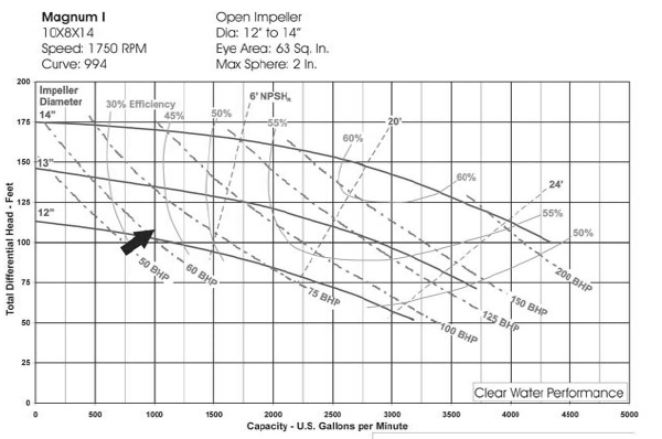
Centrifugals must be sized using maximum values anticipated, to ensure that they can perform without cavitation and that the driver is adequately sized. If there is a possibility that the contractor would add a third cone and flow at 1500 gpm, the pump must be sized to handle up to 1500 gpm (this would also affect line velocities and friction losses). Motors must be sized for maximum mud weight. For this example, assume 1000 gpm to be the maximum flow rate and 16 lb/gal mud to be maximum mud weight. A pump to produce 1000 gpm at 107 feet TDH is required. This operating point is marked on attached curves (see Figure 1. – 6.).

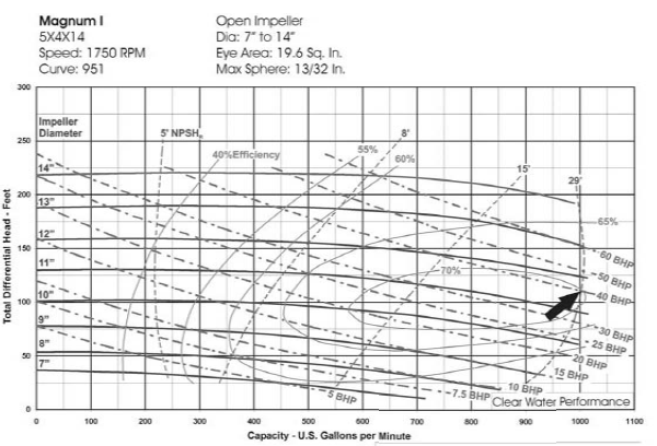

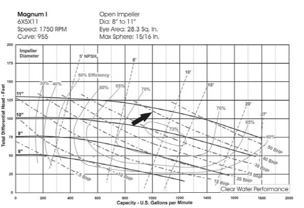
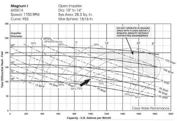
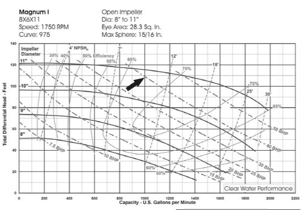
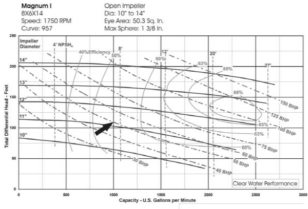

Following are possible centrifugal pump selections for this application:
| 5×4×14 | 11.50"Impeller | 39 hp (water) | 29' NPSHR | 70% Efficiency |
| 6×5×11 | 10.75"Impeller | 39 hp (water) | 9' NPSHR | 71% Efficiency |
| 6×5×14 | 10.75"Impeller | 39 hp (water) | 10' NPSHR | 70% Efficiency |
| 8×6×11 | 10.75"Impeller | 40 hp (water) | 10' NPSHR | 67% Efficiency |
| 8×6×14 | 11.25"Impeller | 50 hp (water) | 7' NPSHR | 54% Efficiency |
| 10×8×14 | 12.25"Impeller | 71 hp (water) | 16' NPSHR | 40% Efficiency |
With six different pumps that meet the criteria, it is important to select the pump that best meets the application. First consider where on the curve the operating point is located:
-
5×4×14: Located at the end of the curve. NPSHR is very high. If this pump is used, cavitation is likely due to insufficient NPSHA. Even given sufficient NPSHA, if additional cones are added, mud temperatures rise, or if the desander cone wears, the pump could not handle the increased volume required. This would be an unacceptable sizing choice.
-
6×5×11: Most efficient pump for the application. An impeller diameter of 10.75 inches is near the maximum impeller diameter for this pump. If there were any miscalculation of friction losses or if the pump were to be relocated farther from the equipment, there would not be a way to significantly increase discharge head. This would be a fair choice.
-
6×5×14: Located in the center of the curve near the best efficiency point. Discharge head can be increased or decreased by changing impeller size. NPSHR is low. The 6×5×14 costs less than larger pumps. This would be an excellent choice.
-
8×6×11: Comments are the same as for 6×5×11.
-
8×6×14: Located left of the best efficiency point. This pump would perform well in the application but would require more energy than the 6×5×14, resulting in higher operating costs. Some contractors may still wish to use this pump if they are utilizing a majority of 8×6×14’s because they could reduce their spare-parts requirements. However, a different-size pump would only require an additional impeller and maybe casing held in stock. If space is available for spares, this is not a good reason to make this selection. This would be a good choice for this application.
-
10×8×14: Located at the very far left of the curve, and a 10-inch suction line would have a line velocity below the recommended minimum. Horsepower requirements are much higher than for other pumps. Although this pump would function in this application, it would be a bad choice.
The 6×5×14 is the best pump for this application.
Knowing the SG of the fluid is necessary to determine the hp required. Maximum mud weight in this example is 16 lb/gal. To determine SG, use the following formula:
SG = (lb/gal) / 8.34; therefore, 16/8.34 = 1.92SG
where 8.34 lb = weight of 1 gallon of water. Horsepower required:
SG × hp for water=1.92 × 39 = 74.88 hp.
A more accurate hp formula is as follows:
hp = (gpm × feet of head × SG)/(3960 × eff)
therefore:
74.11 = (1000 × 107 × 1.92) / (3960 × .70)
Motors are available in 75 hp, but it is advisable to select a 100-hp motor (if using an electric driver). A 100-hp motor would offer flexibility for the package, compensate for any errors, increase flow rates against pipe or equipment wear, and allow the contractor to exceed 16 lb/gal if future requirements dictate.
Normally a motor with a 1.15 service factor (SF) would be utilized. This means that a 75-hp motor is capable of producing.
(75)(1.15) = 86.25 hp.
However, the SF of a motor is intended for intermittent service, and running in the SF continuously will shorten the life of the motor.
If the pump delivers insufficient head, the equipment being fed may not be operating properly and could be damaged. If the pump delivers excess head, flow rates will increase and may cause motor overload. Excessive inlet head to some equipment can also cause premature wear, equipment failure, and/or improper operation.

One Reply to “CENTRIFUGAL PUMP AND STANDARD DRILLING EQUIPMENT”
Comments are closed.