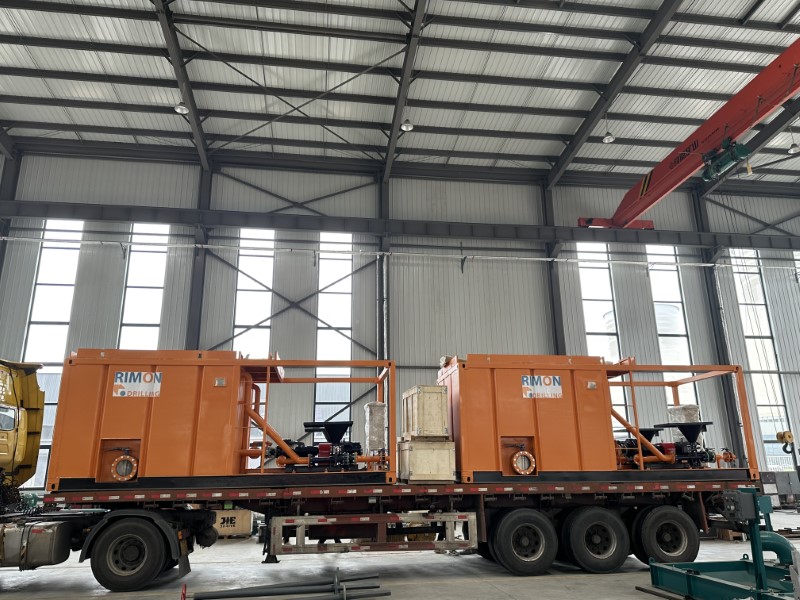
Mud Agitator Impeller Size Calculation (Turnover Rate (TOR))

agitator with impeller

Turnover Rate (TOR)


Impeller sizes are determined by calculating the TOR (sometimes called the time of rollover) for each compartment. This is the time, in seconds, required to completely move the fluid in a compartment (Table 10.1) and can be calculated by knowing the tank volume and impeller displacement:

TOR = (Vt⁄D)×60

where

. Vt=tank volume, in gallons or liters
. D=impeller displacement, in GPM or LPM (as displayed in Table 10.2).

For flat and canted impeller applications, TOR should range between 40 and 85 seconds. As the TOR approaches 40 seconds, the chance for vortex formation and possible air entrainment increases. At values greater than 85 seconds, the proper suspension may be jeopardized and solids will begin to settle.

Table 10.1 Typical Turnover Rate Values, in seconds

Impeller TypeRemovalAdditionSuctionReservePill
Canted/flat50-7550-7565-8550-8040-65

Table 10.2
60-Hz Impeller Displacement D Values

Diameter Flat Canted Contour
InMmGpm1pmGpm1pmGPM1pm
20508105139789093441N/AN/A
246101941737416456226N/AN/A
2871128391074624689341586122185
32813463517543376414247N/AN/A
389657342277896343240081060440136
401016841131836728427570N/AN/A
421067N/AN/AN/AN/A1394052762
4411181130042771992837577N/AN/A
451143N/AN/AN/AN/A1681263633
481219144015450812512473582002075776
521321186307051516100609392485294063
541372N/AN/AN/AN/A27602104475
561422N/AN/AN/AN/A30353114887
601524N/AN/AN/AN/A36567138404
641626N/AN/AN/AN/A43533164771

For contour impeller applications, values must be significantly faster (i.e., smaller numbers) to achieve the same results, but because of the impeller design, air entrainment is less probable. In symmetrical compartments, the fluid has a nearly equal distance to travel from the center of the impeller shaft or from the impeller blade tip before it contacts the vessel wall. Agitators should be placed where the shaft is centered in the tank or compartment.

When defining the area in which to mix, it is best to work with symmetrical shapes like squares or circles (as viewed in a plan drawing or overhead view of the tank layout). Rectangular tanks should be converted to nearly square compartments if possible. Maximum fluid working volumes in compartments should not be higher than 1 foot (about 3⁄10 m) from the top of the tank. This will allow for a little extra capacity in emergencies, slightly out of level installations, and/or fluid movement on floating rigs.

Working volume for square or rectangular tanks is calculated by knowing dimensional values for length (L), width (W), and height (H; in feet for gallons, in meters for liters):

For gallons:

Vt = L × W(H− 1)× 7.481

The working volume for round tanks with flat bottoms is:
For gallons:

Vt = Π r²(H−1)× 7.481

For liters:

Vt = Π r²(H−0.3)×  1000

For round tanks with dish or cone bottoms, calculations for working fluid volume are based on straight wall height (i.e., this height is measured from the tank top to where the tank joins the cone or dish at the bottom). This leaves adequate free space above the maximum fluid operating level. In all cases, if H<5 feet (1.5 m), a radial flow impeller should be specified.

Trip Tank Function

A trip tank is a typical cylindrical or rectangular tank (in a Vertical position). The trip tank storage or receive drilling fluid (depends on which operations you did: pulling out of the hole or tripping into the hole).

The trip tank is used not only for drill pipe or drill collar but also can be used to monitor the filling of the well (when you pull out any kind of tool from the borehole). Another function of the trip tank is used to monitor the displacement of each tubular/tool ran into the borehole. In some operations, the hole can be monitored with the trip tank when there’s no tool/tubular is into the borehole (for example, when you logging operations you can watch if the hole is taking or over displacing fluids).

The TT (trip tank) must have 2 types of measurements (mechanical and optical/electronic/sonar type), that’s mean, when you are using the TT you must know how the fluid level is inside the TT.
Typical TT have 20-40 bbls of capacity (depends on each drilling contractors. but you can find useful information in the API specs or IADC specs bulletins)

The trip tank is located at the mud pits, near the shale shakers, it is used when the drill pipe is pulled out of the wellbore, because the drill pipe ocupies a volume inside the hole, and that volume needs to be replaced so the well is always filled with mud to mantain pressure as you said previously.

Drilling contrator use the trip tank to know the volume occupied by the steel (drill pipe + drill collar) to add in the well when they puuled out and to detect any kick off.

Trip Tanks are often circulated over the hole while tripping and loss are monitored usually electronically from the driller’s console. Every 5 stands the calculations have to be quickly made to make sure the hole is taking the proper amount of fluid. Not filling properly would indicate a gas kick or swabbing the hole as well as a few other possibilities. A small tank (trip tank) is used because it is easier to get a more accurate reading than if you left the flow line lined up on the pit system.

Trip tank delivery