

The rotating separator process is based on a different principle than the shale shaker process. The mud line flow is fed into the slowly rotating separator. The drilling fluid contaminated with drilled cuttings is fed into the centre of a screen coated drum as shown schematically in Fig. 1. The outside of the drum is connected to an under-pressurised ventilation system.


The drilling fluid is efficiently removed from the cuttings by the combined use of gravity and the pressure difference across the screen. A conveying device mounted on the inside of the slow rotating drum forces the cuttings to move along a very long screen section. Therefore, the individual cuttings particles handled by the Rotating separator are exposed to a larger screen area than the particles separated on conventional shale shakers. The individual cuttings particles are treated with care. There is no wear of the particle induced from any applied vibrating motion.


A carefully selected series of fluid jets are used to prevent plugging of the screen openings. Since the total screen area is large and plugging of the screen openings is avoided, the flow capacity of the device is high.
The ventilation system, used to optimise solids control properties, prevents any release of hydrocarbon damp or mist to the atmosphere in the shaker room. Therefore, the use of the rotating separator principle significantly improves several occupational hygiene issues in the shaker room area. The rotating separator itself, as used in the tests, is shown
schematically in Fig. 2.


Rotating separator performance experiments
Indoor tests have been conducted with both water based and oil based drilling fluids containing cuttings. The drilling fluids were field samples collected from Statoil operated drilling outside Northern Norway. The initial tests were conducted with field cuttings. However, during the enterprise of recycling these cuttings particles, the particles were slowly dissolved into the water based drilling fluid and became a part of the drilling fluid. Therefore, in the later series of tests a selection of gravel and sand with similar particle size distribution and similar form as the real cuttings was used. Furthermore, the drilling fluid volume became significantly viscosified by dissolved cuttings particles and had to be
treated.
In the tests the performance of the Rotating separator has been compared with the performance of a conventional shale shaker mounted on a parallel line. Cuttings are fed into the system in a way such that the cuttings concentration is equal in the flow through the Rotating separator and the flow through the shaker.

Flow capacity
In a series of tests, similar screens were used in the rotating separator and on the conventional shaker. Since these tests were comparative there was no need to specify the screen design in detail. The maximum flow capacity was measured for each screen size. A comparison between the flow capacity for the rotating separator and the conventional shale shaker is conducted for each screen size.
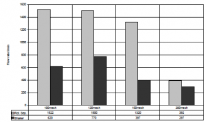
The results from the tests where water based drilling fluid is circulated through 100 and 120 mesh screens with square openings are shown in Fig. 3. The tests were conducted at three different temperatures. As can be seen from the figure, for all the three temperatures the flow capacity was higher for the rotating separator than for the conventional shaker. The improvement in flow capacity was higher than 60% on the tests with 100 mesh screens for all the tests.


A series of experiments have been conducted with oil based drilling fluid. In the experiments conducted at 40oC, the plastic viscosity was 32cP and the API yield point was 5Pa. The capacity of the rotating separator was compared with the capacity of the conventional shaker while pumping drilling fluid containing a small portion of cuttings. As can be seen from Fig. 4, the capacity of the rotating separator exceeds significantly the capacity of the conventional shaker at screen sizes up to 150 mesh. At 200 mesh the improved capacity of the rotating separator was less; roughly 30%.


The rotating separator has not yet the optimised design with respect to obtain maximum flow capacity. Outside the screen there is a slotted plate which appear as a support for the screens. The number and sizes of the slots in the slotted plate can be increased significantly. When this slot area is increased the flow capacity of the rotating separator is anticipated to be similarly increased.
During drilling the cuttings load will have an impact on the maximum flow capacity for the different devices. Therefore a series of capacity test were performed where synthetic cuttings were added. The cuttings loading rate was selected to simulate a drilling rate of 60 m/h in a 12 ¼” section on a rig with three primary solids control devices. As can be seen from Fig. 5, the maximum flow capacity of the rotating separator is more than twice that of the conventional shaker for a screen size of 150 mesh or coarser. For finer screens the capacity of the different machines approximates each other. Still, the light opening of the screen support layer in the rotating separator can be significantly increased. This will yield an increase in the rotating separator flow capacity also for finer screens.

There is always a discussion whether the shaker had been operated under optimum conditions. Therefore, it can not be concluded that the rotating separator has better flow capacity than a general shale shaker; albeit the test results for the rotating separator were all better. The tests, however, do demonstrate that the flow capacity is not significantly less than on a conventional shale shaker.
Oil on cuttings
While running the flow capacity experiments the oil on cuttings was measured. Typically, in field operations, the oil on cuttings would be in the range 20-40% by volume, dependent on the screen opening size. Coarse screen size give dryer cuttings than fine screens since there is less fine fraction with the very large surface area.
Oil on cuttings values for the 120 mesh experiments are shown in Table 1. The experiments were conducted at the maximum flow rate for the conventional shaker and the maximum flow rate for the rotating separator. All the data are within the expected range with the rotating separator. results generally slightly better than the conventional shale shaker results.
Table 1. Oil on cuttings measurements for the 120 mesh screen experiments (% by volume)
| Equipment | Rot.sep | Rot.sep | Shale shaker |
| Flow rate(1/min) | 1186 | 622 | 622 |
| Oil cuttings | 26.6 | 23 | 30 |
The oil on cuttings content was also slightly better for the rotating separator than for the conventional shaker for the 150 mesh and 200 mesh experiments. These data are shown in Tables 2 and 3. As expected the oil on cuttings is increased when the screen openings become smaller.
Table 2. Oil on cuttings measurements for the 150 mesh screen experiments (% by volume)
| Equipment | Rot.sep | Rot.sep | Shale shaker |
| Flow rate(1/min) | 1325 | 423 | 425 |
| Oil cuttings | 20 | 25 | 25 |
Table 2. Oil on cuttings measurements for the 200 mesh screen experiments (% by volume)
| Equipment | Rot.sep | Shale shaker |
| Flow rate(1/min) | 297 | 297 |
| Oil on cuttings | 33.6 | 34.6 |
The particle size distribution was measured to see if there was a difference in efficiency. As anticipated, since the same screen type was used in both machines, no difference in the particle size distribution was measured.
Hydrocarbon damp and mist
The oil based drilling fluid used in the experiments had been used to drill reservoir sections outside Northern Norway. The drilling fluid was based on a non-aromatic base oil which has very good hydrocarbon mist and vapour properties. During the experiments no hoods or devices made to reduce the hydrocarbon mist and vapour content were used on either machines. The experiments were conducted to visualise the hydrocarbon mist and vapour generated by the two different separation processes themselves.
During the experiments the flow rate was slightly higher in the rotating separator than in the shale shaker. Furthermore, the drilling fluid temperature was 2.2°C higher in the rotating separator tests. Therefore, the experimental conditions were slightly more unfavourable for the rotating separator experiments than for the conventional shale shaker experiments. These experimental data are shown in Table 4.
Table 4. Drilling fluid pumping conditions for the hydrocarbon mist and vapour experiments.
| Equipment | Rot.sep | Shale shaker |
| Flow rate(1/min) | 513 | 500 |
| Oil on cuttings | 56.5 | 54.3 |
The experiments demonstrated that the hydrocarbon mist and vapour collected from the rotating separator were significantly smaller than the similar values collected from the conventional shale shaker. The measurement data are shown in Table 5. The hydrocarbon vapour are reduced to a level approximately a third of that of the conventional shaker. The hydrocarbon mist level has been reduced to an even better level: the mist has not been detected at most locations.
Table 5. Hydrocarbon vapour and mist content of the air close to the equipment. All data in mg/m3. n.d.=not detected
| Position | Rot. sep | Shale shaker | ||
| Mist | Vapor | Mist | Vapor | |
| Front | n.d | 19.23 | 3.67 | 81.73 |
| Front | n.d | 19.31 | 0.45 | 46.14 |
| Front | 0.13 | 18.81 | 3.20 | 79.29 |
| Front | n.d | 13.82 | 0.62 | 42.05 |
| Side | 0.01 | 21.38 | 0.38 | 41.36 |
| Side | n.d | 19.27 | 0.45 | 37.13 |
| Side | 0.28 | 16.68 | 0.42 | 39.45 |
| Side | n.d | 15.21 | 0.92 | 43.78 |
Occupational hygiene specifications require that the hydrocarbon mist values should be less than 0.67 mg/m³ for an environment with 12 hour exposure. The similar values for the hydrocarbon vapour is 33.5 mg/m³. The rotating separator values are better than these values for the current operational conditions with the drilling fluid temperature of 56.5ºC. When the machine design is optimised with respect to occupational hygiene in the production of the rotating separator, these properties are anticipated to be significantly further improved.
Noise level
There are no vibrating parts in the rotating separator design. This has an strong impact on the noise level. The noise level is significantly less than that of the conventional shale shaker. A comparison between the rotating separator and conventional shale shaker noise level at one meter distance from the machines has been performed. It is important to notice that none of these machines have had mounted any noise reducing devices. Therefore, the noise data can not be applied directly to field applications. However, the data shown in Table 6 indicate the potential for noise reduction in the shaker room when the shaker room is equipped with rotating separators units instead of conventional shakers. The noise measurements have identified several noise sources which can easily be modified to reduce the noise level further.
Table 6. Sound pressure level (SPL) measured one meter from the machines, corrected to free field conditions. Values in dBA.
| Rot. sep. | Shale shaker | ||
| SPL | 78 | 87 | |
| Octave
band centre frequency (Hz) |
31.5 | 23 | 64 |
| 62 | 41 | 75 | |
| 125 | 50 | 69 | |
| 250 | 64 | 77 | |
| 500 | 72 | 82 | |
| 1000 | 68 | 84 | |
| 2000 | 71 | 80 | |
| 4000 | 73 | 75 | |
| 8000 | 69 | 71 | |
Operational practice and maintenance
The rotating separator is designed in a manor to simplify changing of screens. Since there are no vibrating parts it is anticipated that the rotating separator screen life will increase compared to the conventional shale shaker. Changing of screens should therefore be simpler and should occur more seldom on the rotating separator than on conventional shale shakers. The rotating separator is equipped with a self-detecting system to determine if there are holes in the screens. If there is a hole in the screen particles will block entrance filters mounted onto the fluid jet pumps used to destroy the drilling fluid gel strengths, and thus, an increase in the pump pressure will be seen.
There is a system connected to the rotating separator, which allows for an automatic cleaning of the screens after finishing a drilling operation. The cleaning media is selected to be compatible with the used drilling fluid: Base oil for OBM and water or brine for WBM.
The rotating separator operational panel can be located on practical locations on the unit or in the shaker room.
Conclusion
A series of experiments have demonstrated that the rotating separator has a better functional performance than a conventional shale shaker with respect to:
- hydro carbon mist and hydrocarbon vapour
- noise
Furthermore, the experiments have shown that the rotating separator has an excellent flow capacity. It is also shown that an offshore version of the rotating separator can be made with further improvements on all these above mentioned properties.
Fast Reading
Occupational hygiene requirements for operations on the Norwegian shelf when drilling with oil based drilling fluids favours the use of enclosed system for solids control. Personnel working with shale shakers are often exposed to a base oil mist and vapour at an unacceptable level. A principle with the use of rotating separators as an alternative to shale shakers was therefore developed.
This topic describes the principle with rotating separators as an alternative to shale shakers in detail. The paper focuses on tests where the separator efficiency from the rotating separator is compared with the efficiency from conventional shakers. The separator principle is to feed the drilling fluid with cuttings from the mud line into a slowly rotating separator that forces the cuttings to move along a very long screen section with selected screen sizes. The drilling fluid is effectively removed from the cuttings since the area outside the screen is slightly vacuumed. This principle result in an apparatus with an effective solids separation being among the better separation results obtained by conventional shale
shakers.The topic also describes the improvement on the occupational hygiene and the environmental impacts resulting from the use of the rotating separator compared to the current status from using conventional shakers. Norwegian drilling equipment standards require that the noise level from a device in the drilling area should be less than 83 dB. The paper describes how this requirement is satisfied and that the noise level is far below the requirement level when using the rotating separator.
