

The mixing system makes possible improvements and presents case histories of field applications.
Fracturing operations have been improved by
(1) Mixing fracturing slurries under microprocessor control,
(2) Applying new baffle and agitator design concepts, and
(3) Using new methods for achieving rapid material wetting.
With these new methods, high sand concentration slurries can be mixed in high-viscosity gels, at low or high rates. A ramped pumping schedule can be used to help achieve greater fracture length since pumping stoppage caused by “sandout” can be delayed or prevented.
Introduce
A long-standing problem within the well servicing industry is that of mixing proppant slurries that are of essentially homogeneous uniformity. When mixing slurries of high proppant concentration at high rates, it is common to entrain excessive air in the slurry, to have poor dispersion of solid material, and to have inadequate solids wetting. Conventional agitator designs typically will not adequately mix high proppant concentrations, because the slurry becomes more proppant concentrations, because the slurry becomes more viscous as proppant concentration rises, reducing the agitation intensity.
Research was performed to develop equipment that would mix high proppant concentrations in non-Newtonian gel at low and high pumping rates. The specific objectives of this research were
(1) to gain information necessary for design of a full-scale fracturing proppant slurry mixing system and
(2) to design a proppant slurry mixing system and
(3) to design a mixing system to produce homogeneous, high-proppant-concentration slurry.
REVIEW OF LITERATURE
Mixer performance is typically expressed in terms of fluid velocity generated, total pumping capacity of the impeller, total flow in the tank, or in terms of an evaluated criterion. If the application is relatively simple and easily analyzed, a detailed examination of complicated fluid mechanics in a mixing tank will be unnecessary. When the process is complex, a thorough examination of shear rates and tank turbulence may be required. Sometimes it is possible to express a complex mixing process in terms possible to express a complex mixing process in terms of bulk velocity and pumping-capacity relationships.
Significant progress was made by Dickey and Hicks in organizing the principles of fluid motion and presenting mixing design concepts and procedures. Also presenting mixing design concepts and procedures. Also discussed are the effects of non-Newtonian fluids on agitator performance. A design procedure that may be used for th design of turbine agitators in the chemical process industry was presented by Hicks Morton, and Fenic. Gates, Morton, and Fondy discussed solids suspension surface control, and shear rate for application involving dry solids incorporation. Qualitative effects of liquid viscosity, vessel volume, flow, and shear have been presente by Penny. These procedures and techniques presente by Penny. These procedures and techniques were utilized in the current work to make preliminary estimates of mixing system specifications.
DESIGN CONSIDERATIONS
The purpose of mixing fracturing proppant slurries is to create a pseudo-homogeneous mass of solids and liquids that is reasonably stable. Well-mixed slurry made from a fracturing gel should remain in slurry form for a time before proppant settling occurs. These gels are usually very viscous and non-Newtonian in nature; they will thin under shearing conditions, a property that makes the design of the mixing tank and agitator system extremely critical.


To achieve the goal of uniform suspension of proppant in the fracturing gel, agitation within the tank must be intense enough to create the required fluid turbulence to complete the mixing job on a timely basis. The mixing job is continuous, at flow rates up to 7bbl/min. While larger mixing tanks increase the fluid residence time in the tank and increase the time available to do the mixing, the volume of the tank is constrained by installation on mobile equipment.
Power requirements are driven by the time available to perform the mixing task; less time available will dictate an increase in mixer power to maintain a constant process result. Further complicating the mixing task are the high viscosity, non-Newtonian, and shear-sensitive fluids used. Mixing of these fluids normally requires a large, slow speed agitation system to provide uniform slurry movement from top to bottom of the mixing tank. The diameter of the agitator must be large enough in relation to the mixing tank diameter to provide approximately the same slurry velocity throughout the mixing tank. A more uniform shear rate within the tank is the result, thus minimizing dead spots or low turbulence areas.

To accomplish the difficult task of solids wetting, proppant-and gel must enter the mixing tank at approximately the same place and must be subjected to intense turbulent mixing to prevent formation of proppant agglomerates. As the proppant input rate increases and increases the amount of proppant to be wetted, intensity of agitation must also increase to complete the wetting process and achieve a constant process result. As the intensity of agitation increases, the input power required will increase.
As proppant concentration rises, effective viscosity in the mixing tank increases, driving the need for an increase in agitation. Since mixing tank size is a function of mobility requirements and constraints, there is very little flexibility in design allowed. Diameters of agitators should be made as large as possible in consideration of the shear sensitivity of the fluids to be mixed. Uniformity of shear is considered to be more important than level of shear.

With mixing tank size and agitator size fixed, the design task was to experimentally determine the following:
- Number and type of agitator
- Best location for incoming proppant and fracturing gel to enter the mixing tank to enhance initial sand settling.
- Agitator speed and input power requirements for the range of throughput flow rates and proppant concentrations.
Table 1


Table 2
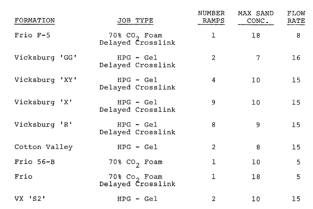

Table 3


DEVELOPMENT
The development approach used was to build a bench scale mixing system of approximately one-half scale. From this mixer, a testing process and initial design criteria for a full-scale system were determined. All bench-scale tests were made using 20/40 mesh sand and fracturing fluid containing 40 lb/M-gal HPG gel.
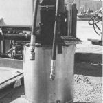
Shown in Fig. 1 is the bench-scale mixing tank. In Fig. 2 is a general schematic of the full-scale mixing tank and agitator system which is the result of extensive testing on the bench model. The bottom agitator is an axial flow type (flow through the center) that prevents proppant from settling in the tank bottom..
Fig. 3 shows an unconventional top agitator that flows radially outward as well as flowing downward through the middle. Extensions on all blades are pitched to cause upward flow. This blade extension provides flow velocity to increase turbulence at the top of the tub. Proppant and clean liquid enter there and initial wetting occurs. If the slurry is not turbulent, dry proppant stacks up, leading to a complete “sandout” of the mixing system. Baffles are necessary to prevent high-proppant-concentration slurry from merely spinning in the tub as a solid mass.
Figure 4 is a plot of sand concentration vs. time. This plot is an example of the type data collected with the bench-scale system. It is at a flow rate of 5bbl/min and shows that a sand concentration of approximately 21 lb/gal was achieved for more than 3 minutes.


FULL-SCALE SYSTEM
Rautzen et al.showed that dimensional analysis could be used to scale up from small-scale mixing tests and duplicate the fluid behavior necessary to achieve equivalent process results in large-scale equipment. Geometric, kinematic, and dynamic similarity can’t always be achieved at the same time.
To develop the current full-scale mixing system, geometric similarity was used to scale up the geometric parts. Various lengths within the system were scaled up by a fixed ratio. The ratio was chosen to accommodate a mixing tank, of a diameter approximately equal to its fluid depth, that would fit within the constraints of mobile equipment. Tank volume allowed within these criteria was 9 bbl. In this configuration, design flow rates ranged from 60 seconds at 9 bbl/min to 7.2 seconds at 75 bbl/min.
Agitator speed was adjusted on the large-scale system to achieve the desired process result. An automatic agitator speed control system was incorporated into the design of the new blending equipment on which this mixing system is utilized. The control system increases the agitator speed as proppant concentration increases and as the throughput flow rate increases in an attempt to keep the process result the same.
A full-scale mixing system was built, tested, then utilized as a part of new automatic remote controlled blending equipment (Fig. 5). Figures 2 and 6 are schematics of the mixing system showing the mixing tank, agitators, proppant and fluid entrance points, and slurry exit points.
Data collected during full scale testing are shown in Figures 7 through 11. All full-scale testing used 20/40 mesh sand and fracturing fluid containing 40 lb HPG/1000 gal. These figures show sand concentration vs. time. Fig. 6 shows that a sand concentration of 21 lb/gal was achieved at a flow rate of 10bbl/min. Fig. 7 shows a stepped increase in sand concentration up to 18 lb/gal. Fig. 8 shows a continuous increase in sand concentration to 18 lb/gal, then holding 18 lb/gal for 1-1/2 minutes. Fig. 9 shows a continuous run to a sand concentration of 19 lb/gal. Fig. 10 is for a test at a slurry rate of 50 bbl/min and sand concentration ramped up to 8 lb/gal.
FIELD DATA
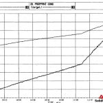
The slurry processing equipment using the full scale mixing unit has completed 7 5 fracturing jobs. Tables 1 and 2 show a typical job schedule stage description and job schedule stage information. 2. Figure 12 is a plot of proppant concentration and density vs. job time. This job had a 1 to 6 lb/ gal ramp in 60 minutes and a 6 to 10.5 lb/gal ramp in 15 minutes. There was 8 minutes of pumping at 10.5 lb/gal at a flow rate of 15bbl/min. Figure 12 shows the two ramps and that maximum proppant concentration variability was ±0.15 lb/gal. Various field jobs and data are listed in Table 3.

CONCLUSIONS
- A reliable mixing system for fracturing slurries has been built. This system will mix proppant concentrations of up to 21 lb/gal.
- Existing information and scaling coupled with proper test work was utilized to design this fracturing slurry mixing system.

One Reply to “Mixing System for Fracturing Fluid”
Comments are closed.