


The function of the centrifugal pump casing is to:
- Direct fluid into the eye of the impeller through the suction inlet.
- Minimize fluid recirculation from impeller discharge to impeller suction.
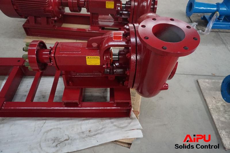
- Capture fluid discharge from the impeller in the case volute to most efficiently utilize work performed by the impeller and direct fluid away from the impeller. (See Picture 1. and 2.)


The centrifugal pump’s impeller performs useful work and increases the head of the fluid. The casing consumes part of the work imparted to the fluid and creates head losses due to friction, eddies, and other flow characteristics. A good casing design will minimize the losses, as opposed to a bad casing design. However, no casing design will increase pump head above what exists at the discharge of the impeller. Typically a centrifugal pump casing is designed so that the suction flange is one or two pipe sizes larger than the discharge flange. This is done to manage velocity of the fluid as it approaches the impeller inlet and also to minimize friction losses ahead of the pump. Excessive losses on the suction side of a pump can cause severe and rapid damage to the centrifugal pump impeller and casing.


As fluid discharges from the impeller into the case volute, it has increased in head value by the amount of work imparted by the impeller. Since fluid will naturally flow in the direction of least resistance, it will tend to flow back (recirculate) toward the suction inlet, where fluid entering the impeller is at a relatively low head. In order to prevent this recirculation, a restriction must be created between the impeller and casing to minimize flow back to the suction and cause the fluid to flow out the discharge. In this example, with an open impeller, that restriction is the very close clearance (gap) between the impeller and the casing wall. This gap is typically 0.010 to 0.030-inch wide.
Two major factors in determining gap size are :
- desired performance (the smaller the better).
- minimum allowable clearance to prevent impeller rubbing during pump operation.
This works well when the pump is in a new condition but eventually the impeller and casing will begin to wear and the gap size will increase, allowing more fluid to recirculate to the suction side of the impeller. Eventually pump performance will deteriorate to the point that an adjustment to the impeller location will have to be made (if possible in the pump design) or the impeller and casing will have to be replaced in order to restore the pump’s original performance.
As shown in Picture 1 and 2, fluid is discharged from the impeller into the case volute. One aspect of a good casing design is that the volume of the volute is sized to match the volume flow through the impeller so that fluid velocity in the volute is somewhat less than fluid velocity exiting the impeller. This reduction in velocity is where a portion of the overall pump head is generated. If velocity reduction is too great, excessive shock losses and eddy currents in the volute will degrade pump head output. If velocity reduction is too small, excessive friction losses will occur in the volute that will also degrade pump head output.
In Picture 2, the part of the casing called the cutwater can be seen. This is where fluid is guided into the discharge outlet and led away from the pump. The cutwater must be accurately located relative to the impeller and angled to minimize flow disruption as fluid exits the casing. A cutwater that is too close to the OD of the impeller will cause a pressure pulse to be created as the impeller vane passes by the cutwater. This momentary high-pressure pulse will disrupt flow and cause pump output to degrade. Conversely, a cutwater that is too far from the impeller will allow too much fluid to pass by the outlet and simply recirculate within the case volute and thereby reduce pump output. The angle of the
cutwater must match the flow path of the fluid as it exits the casing. If it does not, eddy currents will be created that degrade pump performance.
In summary, the impeller of a centrifugal pump is designed to impart kinetic energy to a fluid, raising the head value of the fluid to accomplish a specific goal. The pump casing design must be matched to the impeller to most efficiently guide fluid into and away from the impeller. When these components are properly designed, fluid will flow smoothly through the machine with minimal recirculation and losses caused by eddy currents and friction that can degrade pump output head.

2 Replies to “CASING OF CENTRIFUGAL PUMP”
Comments are closed.