Shale shakers are components of the solids control systems. Shale shaker mainly used in the oil and gas drilling industry. Shale shaker is the first phase of a solids control system on a drilling rig, and are used to remove large solids (cuttings) from the drilling fluid (“mud”).
Historically, the progression of the design of shale shakers has been toward allowing the use of finer screens. Shale shakers have developed through the years from relatively simple, uncomplicated designs to today’s complex models. In fact, this evolutionary process has seen several distinct eras of shale shaker technology and performance. These developmental time frames can be divided into four main categories:
1. Unbalanced elliptical motion
2. Circular motion
3. Linear motion
4. Balanced elliptical motion
The eras of oilfield shaker (and screening) development may be defined by the types of motion(s) produced by the vibrators and their associated machines.
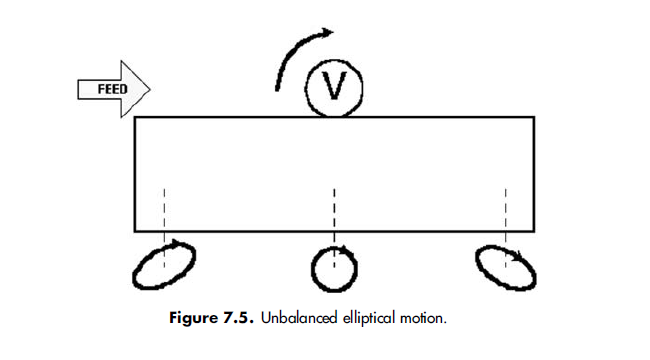
If a single rotating vibrator is located away from the center of gravity of the basket, the motion is elliptical at the ends of the deck and circular below the vibrator (Figure 7.5). This is an unbalanced elliptical motion. If a single
rotating vibrator is located at the center of gravity of the basket, the motion is circular (Figure 7.6). Two counterrotating vibrators attached to the basket are used to produce linear motion (Figure 7.7).
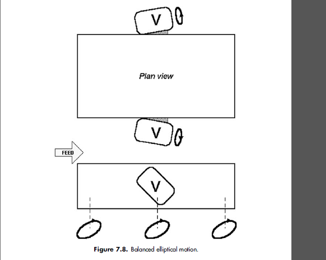
When placed at an angle to the basket, two counterrotating vibrators can produce a balanced elliptical motion (Figure 7.8).
1. Unbalanced Elliptical Motion Shale Shakers
In the 1930s, unbalanced elliptical shale shakers were adapted by the oilfield. These first shakers came from the mineral ore dressing industries (e.g., coal, copper) with little or no modifications. They were basic, rugged, and mechanically reliable but were generally limited to API 20 and coarser screens.
In an unbalanced elliptical motion shaker (Figure 7.5), the movement of the shaker deck/basket is accomplished by placing a single vibrator system above the shaker deck. That is, the mechanical system of a spinning counterweight (or an elliptically shaped driveshaft) is installed above the center of gravity of the deck. The resulting motion imparted to the bed is a combination of elliptical and circular. Directly below the vibrator, the motion of the basket is circular, while at either end of the deck the motion is elliptical.
The orientation of the major axes of the ellipses formed at the feed end and the solids-discharge end of the basket has a major impact on solids conveyance. Specifically, it is desirable for the major axis of the ellipsoidal trace to be directed toward the solids-discharge end. However, the orientation of the major axis of the ellipse formed at the solidsdischarge end is just the opposite; it is directed backward toward the feed end. This discharge-end thrust orientation is undesirable, since it makes discharging solids from the shaker more difficult (Figure 7.9). To assist in solids conveyance, the deck or last screen is tilted downward (Figure 7.10) or the vibrator is moved to the discharge end. Moving the vibrator toward the discharge end reduces the fluid capacity and reduces the screen life of the end screen significantly. This also reduces the residence time of the feed slurry on the screening surface. Advertisers of this style of motion touted the fact that the reverse-tilted ellipse allowed solids to remain on the screen longer, thereby removing more liquid.
Early elliptical motion shale shakers used hook-strip screens that were manually tensioned. A series of tension rails and tension bolt spring assemblies were used to pull the screens tightly over the support bars to ensure proper tightening. Pretensioned screens and pretensioned screen panels were not introduced until the 1970s and even then were not commonly used on elliptical motion units.
As with most engineered products, compromises have been made. Achievement of an acceptable balance is sought between the amount of feed slurry the shaker can handle and its ability to effectively move solids along the screen deck. The early elliptical motion shakers typically had one screen surface driven by a motor sheaved to the vibrator with a belt drive. Later models of this design employed additional screen area and/or integral vibrators to increase flow capacity. These shakers were
capable of processing drilling fluid through API 60 to API 80 screens.
Unbalanced elliptical motion shale shakers are compact, easy to maintain, and inexpensive to build and operate. They use relatively coarse screens (API 60 to API 80), and for this reason are frequently used as scalping shakers. Scalping shakers remove large solids or gumbo and reduce solids loading on downstream shakers.
2. Circular Motion Shale Shakers
Circular motion shakers were introduced in 1963. These shakers have a single vibrator shaft located at the center of mass of a horizontal basket. A motor drives a concentric shaft fitted with counterweights, which provides pure circular motion along the entire length of the vibrating deck. This feature improves solids conveyance off the end of the deck compared with unbalanced elliptical designs. The circular motion transports solids along a horizontal screen, thus reducing the loss of liquid without sacrificing solids conveyance.
Circular motion units often incorporate multiple, vertically stacked decks. Coarse screens mounted on the top deck separate and discharge the larger cuttings, thus reducing solids loading on the bottom screens. These multiple deck units allowed the first practical use of API 80 to API 100 screens.
Flowback trays (Figure 7.11) introduced in the late 1970s direct the slurry onto the feed end of the finer screen on the lower deck. The tray allows full use of the bottom screen area to achieve greater cuttings removal with less liquid loss. Even with these units, screens are limited to about API 100 by the available screening area, vibratory motion, and screen panel design. If bonded screens are used, screens as fine as API 150 have been used with flowback trays. Screens on the circular motion units are installed either overslung or underslung. The open hook strip screen is tensioned across longitudinal support members. Both designs have advantages and disadvantages. Overslung screens have reasonable screen life, but the drilling fluid tends to channel to the sides. On underslung screens, drilling fluid tends to congregate around and beneath the longitudinal support members. Grinding of this accumulation of drilled solids between the rubber
support and the screen tends to reduce screen life. To overcome this screen life reduction, rubber supports with flatter cross sections are used and strips are installed between the rubber support and the screen.
In the 1980s some circular motion machines began to be fitted with repairable bonded underslung screens that increased screen life and fluid throughput. Even though the use of repairable bonded screens reduced the available unblanked area, the detrimental effect on fluid capacity was more than offset by the use of higher-conductance screen cloths and larger bonded openings.
3. Linear Motion Shale Shakers
The introduction of linear motion shale shakers in 1983, combined with improved screen technology, resulted in the practical use of API 200 and finer screens. Linear motion is produced by a pair of eccentrically weighted, counterrotating parallel vibrators. This motion provides cuttings conveyance when the screen deck is tilted upward.
Linear motion shakers have overcome most of the limitations of elliptical and circular motion designs. Straight-line motion provides superior cuttings conveyance (except with gumbo) and superior liquid throughput capabilities with finer screens. Linear motion shale shakers generally do not convey gumbo uphill. They can effectively remove gumbo if they are sloped downward toward the discharge end. The increased physical size of these units (and an accompanying increase in deck screen surface area) allows the use of even finer screens than those used on circular or elliptical motion shakers.
Screening ability is the result of applying the energy developed by a rotating eccentric mass to a porous surface or screen. The energy causes the screen to vibrate in a fixed orbit. This transports solids across the screen surface and off the discharge end and induces liquid to flow through the screen.
In conventional unbalanced elliptical and circular motion designs, only a portion of the energy transports the cuttings in the proper direction, toward the discharge end. The remainder is wasted due to the peculiar shape of the screen-bed orbit, manifested by solids becoming nondirectional or traveling in the wrong direction on the screen surface. Linear motion designs provide positive conveyance of solids throughout the vibratory cycle because the motion is in a straight line rather than elliptical or circular. The heart of a linear motion machine is the ability to generate this straight-line or linear motion and transmit this energy in an efficient and effective manner to the vibrating bed.
As shown in Figure 7.12, a linear motion system consists of two eccentrically weighted counterrotating shafts. The net effect of each equal eccentric mass being rotated in opposite directions is that resultant forces are additive at all positions along the vibratory trace, except at the very top and bottom of each stroke, resulting in a thrust (vibration) along a straight line—hence, the term linear, or straight-line, motion.
To achieve the proper relationship between the rate of solids conveyance and liquid throughput, the drive system must be mounted at an angle to the horizontal bed. A thrust angle of 90 relative to the screen surface would simply bounce solids straight up and down. Taken to the other extreme, a thrust angle of zero degrees would rapidly move solids but yield inadequate liquid throughput and discharge very wet solids. On most units this angle is approximately 45 to the horizontal.(Figure 7.12).
Some machines have adjustable angle drive systems that can be changed to account for various process conditions (Figure 7.13). If a thrust angle were decreased (for example to 30 to the horizontal), the X component of the resultant vibratory thrust (force) would increase and the Y component decrease. Conversely, building a greater angle would cause the X component to decrease and the Y component to increase.
A larger X vector component of thrust will move solids along the deck faster. A larger Y component vector increases liquid throughput and the residence time of material on the screen. Most manufacturers choose a fixed angle near 45, which gives near-equal values for each vector. This is a logical approach, since the shaker must simultaneously transmit liquid through the screen and convey solids off the screen.
The ability to create linear motion vibration allows the slope of the bed to vary up to a þ6 incline (which affects residence time and therefore shaker performance) and to create a liquid pool at the flowline end of the machine. This allows a positive liquid pressure head to develop and help drive liquid and solids through the finer wire cloths. The deck on most linear motion shale shaker designs can be adjusted up to a maximum of þ6. In some cases, the beds can be tilted down to help in cases in which gumbo is encountered. These movements of bed on skid can be accomplished with mechanical, hydraulic, or combination mechanical/hydraulic systems. On some units these adjustments can be made while the unit is running.
The ability of linear motion to convey uphill allows the use of finer shaker screens. Finer screens allow for smaller particles to be removed from the drilling fluid. Hence,a solids-control system that utilizes finescreen linear motion shakers will better maintain the drilling fluid and improve efficiency of downstream equipment such as hydrocyclones and centrifuges. When screens are tilted too much uphill, many solids are ground to finer sizes as they are pounded by the screen. This tends to increase—not decrease—the solids content of the drilling fluid.
When linear motion shale shakers were introduced, other solidsremoval equipment (like the mud cleaner) was sometimes erroneously eliminated. For a short time, this appeared to be a solution, but solids analysis, discards from other equipment, and particle size analyses proved the need for downstream equipment. Linear motion shale shakers should not be expected to replace the entire solids-removal system.
4. Balanced Elliptical Motion shaker
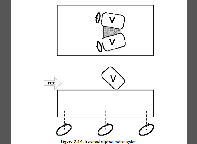
Balanced elliptical motion was introduced in 1992 and provides the fourth type of shale shaker motion. With this type of motion, all of the ellipse axes are sloped toward the discharge end of the shale shaker. Balanced elliptical motion can be produced by a pair of eccentrically weighted counterrotating parallel vibrators of different masses. This motion can also be produced by a pair of eccentrically weighted, counterrotating vibrators that are angled away from each other (Figure 7.14).
The ellipse aspect ratio (major axis to minor axis) is controlled by the angle between vibrators or by different masses of the parallel vibrators.
Larger minor axis angles, or angle of vibrators relative to each other, will produce a broader ellipse and slow the solids conveyance. A thin ellipse with a ratio of 3.5 will convey solids faster than a fat ellipse with a ratio of 1.7. The typical operating range is 1.5 to 3.0, with the lower numbers generating slower conveyance and longer screen life. Balanced elliptical motion shale shakers can effectively remove gumbo if they are sloped downward toward the discharge end in the same manner as the linear motion shakers.
The increased physical size of these units and an accompanying increase in deck screen surface area allows the use of even finer screens than are used on other orbital motion shakers.
In conventional unbalanced elliptical and circular motion designs, only a portion of the energy transports the cuttings in the proper direction toward the discharge end. Balanced elliptical motion transports cuttings toward the discharge end of the screen in the same manner as linear motion. Balanced elliptical motion provides positive conveyance of solids throughout the vibratory cycle.
Gumbo is formed in the annulus from the adherence of sticky particles to each other. It is usually a wet, sticky mass of clay, but finely ground limestone can also act as gumbo. The most common occurrence of gumbo is during drilling of recent sediments in the ocean. Enough gumbo can arrive at the surface to lift a rotary bushing from a rotary table. This sticky mass is difficult to screen. In areas where gumbo is prevalent, it should be removed before it reaches the main shale shakers.
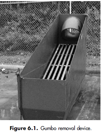
Many gumbo removal devices are fabricated at the rig site, frequently in emergency response to a ‘‘gumbo attack.’’ These devices have many different shapes but are usually in the form of a slide at the upper end of a flowline. One of the most common designs involves a slide formed from steeply sloped rods spaced 1 to 3 inches apart and about 6 to 8 feet long. The angle of repose of cuttings is around 42 °, so the slides have a slope of around 45 °. Gumbo, or clay, does not stick to stainless steel very well; consequently, some of the devices are made with stainless steel rods. Drilling fluid easily passes through the relatively wide spacing in the rods, and the sticky gumbo mass slides down to disposal (Figure 6.1).
Several manufacturers have now built gumbo removal devices for rig installation. One of these units consists of a series of steel bars formed into an endless belt. The bars are spaced 1 to 2 inches apart and disposed perpendicular to the drilling-fluid flow. The bars move parallel to the flow. Gumbo is transported to the discharge end of the belt, and the drilling fluid easily flows through the spacing between the bars. Another machine uses a synthetic mesh belt with large openings, like an API 5 to an API 10 screen. The belt runs uphill and conveys gumbo from a pool of drilling fluid. A counterrotating brush is used to clean gumbo from the underside of the belt. The belt speed is variable so it can be adjusted for the solids-loading and fluid properties.
When linear motion shale shakers were introduced into oil well drilling operations, drilling fluid could routinely be sieved through API 200 screens for the first time. This goal was desirable because it allowed the removal of drilled-solids sizes down to the top of the size range for barite that met American Petroleum Institute (API) specifications.
Circular motion and unbalanced elliptical motion shale shakers were usually limited to screens of about API 80. Drillers soon found, however, that gumbo could not be conveyed uphill on a linear motion shale shaker. The material adhered to the screen. To prevent this, the circular and unbalanced elliptical motion shakers were used as scalping shakers.
The ‘‘rig’’ shakers remained attached to the flowline to remove very large cuttings and gumbo. These were called scalping shakers. Even in places where gumbo might not be present, scalpers were used to prevent very large cuttings or large chunks of shale from damaging the API 200+ screens. These screens have finer wires, which are much more fragile than wire used on an API 20 or API 40 screens. Scalping shakers also had the advantage of removing some of the larger solids that would enter the mud tanks when a hole appeared in the fine screen.
Tests indicated that fitting the scalper with the finest screen possible, an API 80 or API 100, did not result in the removal of more solids when combined with the API 200 on the main shaker. Apparently, shale in that size range would break apart on the scalper into pieces smaller than 74 microns, or it would damage the cuttings enough so that the linear motion shaker screen broke the cuttings. This action resulted in fewer total solids rejected from the system. Scalping shakers should be used as an insurance package to prevent very large cuttings from hitting the fine screens. Scalping shakers, even with an API 20 screen, will still convey gumbo. Frequently, relatively fine screens on a scalping shaker experience near-size blinding. Coarse screens are preferred.
Scalping shakers should be used with either linear motion or balanced elliptical motion shale shakers.Gumbomust be removed before any screen can convey drilled solids uphill out of a pool of liquid. These motions may be used on shakers to remove gumbo if the screen slopes downward from the back tank (possum belly) to the discharge end of the shaker.
Combination shakers are available that mount a downward-sloping screen on a linear motion shaker above an upward-sloping screen with a linear motion. Gumbo will move down the top screen and be removed before the fluid arrives at the lower screen. Again, however, the scalping screen should be a very coarse screen. Some screens reject gumbo significantly better than others. Some screens also convey gumbo more efficiently than others. Manufacturers have a great assortment of screens that have been tested in various regions of the world that experience gumbo attacks. Hook-strip screens with large rectangular openings—in the range of API 12—have been used very effectively in many regions. Experience indicates that the rectangular openings should be oriented so that the long opening is parallel to the flow.
Several important factors control whether to use a shale shaker/scalping shaker to effectively remove gumbo. If the screen deck can be tilted downward, with an articulated deck, gravity will assist gumbo removal. If the older-style unbalanced elliptical motion shaker is used, the fixed downward angle will usually satisfactorily convey gumbo. If the deck angle is flat, like most circular motion machines, the shaker has to generate a sufficient negative, or downward, force vector, normal to screen, to overcome the adhesion factor (or stickiness) of the gumbo so that the screen separates from the solids. If it does not separate, the gumbo is effectively glued to that spot on the screen.
If the drilling fluid is changed to decrease the quantity of gumbo reaching the surface, gumbo removal may not be a problem for main shakers with a high g factor. Scalping shakers, however, will still provide insurance for removal of large cuttings and in case the break in a shale shaker screen goes unnoticed.
Polyurethane shaker screen – frame for scalping shaker