How a shale shaker screens fluid

The primary purpose of a shale shaker is to remove as many drilled solids as possible without removing excessive amounts of drilling fluid. These dual objectives require that cuttings (or drilled solids) convey off the screen while simultaneously most of the drilling fluid is separated and removed from the cuttings. Frequently, the only stated objective of a shale shaker is to remove the maximum quantity of drilled solids. Stopping a shale shaker is the simplest way to remove the largest quantity of drilled solids. Of course, this will also remove most of the drilling fluid. When disregarding the need to conserve as much drilling fluid as possible, the ultimate objective of reducing drilling costs is defeated.
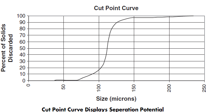
The size of drilled cuttings greatly influences the quantity of drilling fluid that tends to cling to the solids. As an extreme example, consider a golf-ball–size drilled solid coated with drilling fluid. Even with a viscous fluid, the volume of fluid would be very small compared with the volume of the solid. As the solids become smaller, the fluid film volume increases as the solids surface area increases. For silt-size or ultra-fine solids, the volume of liquid coating the solids may even be larger than the solids volume. More drilling fluid is returned to the system when very coarse screens are used than when screens as fine as API 200 are used.
Drilling fluid is a rheologically complex system. At the bottom of the hole, faster drilling is possible if the fluid has a low viscosity. In the annulus, drilled solids are transported better if the fluid has a high viscosity. When the flow stops, a gel structure builds slowly to prevent cuttings or weighting agents from settling. Drilling fluid is usually constructed to perform these functions. This means that the fluid viscosity depends on the history and the shear within the fluid. Typically, the low-shear-rate viscosities of drilling fluids range from 300–400 centipoise (cP) to 1000–1500 cP. As the shear rate (or, usually, the velocity) increases, drilling fluid viscosity decreases. Even with a low-shear-rate viscosity of 1500 cP, the plastic viscosity (or high-shear-rate viscosity) could be as low as 10 cP.
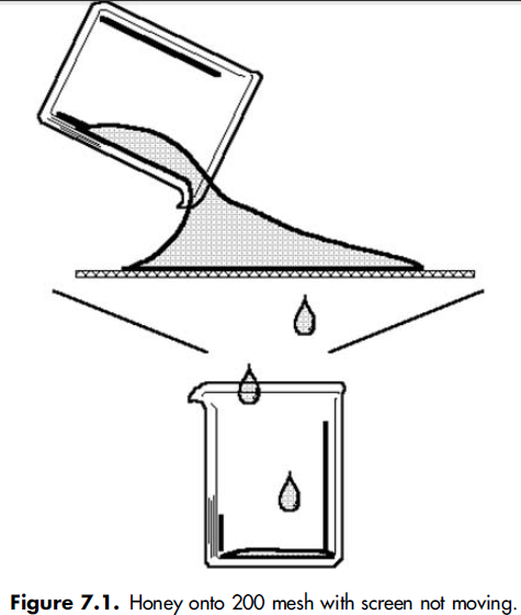
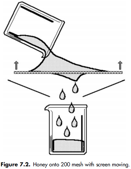
Drilling fluid flows downward, onto, and through shaker screens. If the shaker screen is stationary, a significant head would need to be applied to the drilling fluid to force it through the screen. Imagine pouring honey onto a 200-mesh screen (Figure 7.1). Honey at room temperature has a viscosity of around 100 to 200 cP. Flow through the screen would be very slow if the screen were moved rapidly upward through the honey (Figure 7.2), causing the honey to pass through the screen surface and into a collection device. These forces of vibration affect drilling fluid in the same manner. The introduction of vibration into this process applies upward and downward forces to the honey. The upward stroke moves the screen rapidly through the honey. These forces of vibration affect drilling fluid in the same manner. The upward stroke moves drilling fluid through the screen. Large solids do not follow the screen on the downward stroke, so they can be propelled from the screen surface.
When the screen moves on the downward stroke, the large solids are suspended above the screen and come in contact with the screen at a farther point toward the discharge end of the shaker. This is the reason that the elliptical, circular, and linear motion screens transport solids.

Screens are moved upward through the fluid with the elliptical, circular, and linear motion shale shakers. The linear motion shaker has an advantage because solids can be transported out of a pool of liquid and discharged from the system. The pool of liquid creates two advantages: Not only does it provide an additional head to the fluid, but it also provides inertia or resistance to the fluid as the screen moves upward. This significantly increases the flow capacity of the shaker. The movement of the shaker screen through the drilling fluid causes the screen to shear the fluid. This decreases the viscosity and is an effective component to allow the shaker to process drilling fluid.
The upward movement of the shaker screen through the fluid is similar to pumping the drilling fluid through the screen openings. If the fluid gels on the screen wires, the effective opening size is decreased. This would be the same as pumping drilling fluid through a smaller-diameter pipe. With the same head applied, less fluid flows through a smaller pipe in a given period of time than a larger pipe. If a shaker screen becomes water wet while processing NAF, the water ring around the screen opening effectively decreases the opening size available to pass the fluid. This, too, greatly reduces the flow capacity of the shaker.

SCALPING SHAKERS AND GUMBO REMOVAL

Gumbo is formed in the annulus from the adherence of sticky particles to each other. It is usually a wet, sticky mass of clay, but finely ground limestone can also act as gumbo. The most common occurrence of gumbo is during drilling of recent sediments in the ocean. Enough gumbo can arrive at the surface to lift a rotary bushing from a rotary table. This sticky mass is difficult to screen. In areas where gumbo is prevalent, it should be removed before it reaches the main shale shakers.

Many gumbo removal devices are fabricated at the rig site, frequently in emergency response to a ‘‘gumbo attack.’’ These devices have many different shapes but are usually in the form of a slide at the upper end of a flowline. One of the most common designs involves a slide formed from steeply sloped rods spaced 1 to 3 inches apart and about 6 to 8 feet long. The angle of repose of cuttings is around 42 °, so the slides have a slope of around 45 °. Gumbo, or clay, does not stick to stainless steel very well; consequently, some of the devices are made with stainless steel rods. Drilling fluid easily passes through the relatively wide spacing in the rods, and the sticky gumbo mass slides down to disposal (Figure 6.1).

Several manufacturers have now built gumbo removal devices for rig installation. One of these units consists of a series of steel bars formed into an endless belt. The bars are spaced 1 to 2 inches apart and disposed perpendicular to the drilling-fluid flow. The bars move parallel to the flow. Gumbo is transported to the discharge end of the belt, and the drilling fluid easily flows through the spacing between the bars. Another machine uses a synthetic mesh belt with large openings, like an API 5 to an API 10 screen. The belt runs uphill and conveys gumbo from a pool of drilling fluid. A counterrotating brush is used to clean gumbo from the underside of the belt. The belt speed is variable so it can be adjusted for the solids-loading and fluid properties.

When linear motion shale shakers were introduced into oil well drilling operations, drilling fluid could routinely be sieved through API 200 screens for the first time. This goal was desirable because it allowed the removal of drilled-solids sizes down to the top of the size range for barite that met American Petroleum Institute (API) specifications.

Circular motion and unbalanced elliptical motion shale shakers were usually limited to screens of about API 80. Drillers soon found, however, that gumbo could not be conveyed uphill on a linear motion shale shaker. The material adhered to the screen. To prevent this, the circular and unbalanced elliptical motion shakers were used as scalping shakers.

The ‘‘rig’’ shakers remained attached to the flowline to remove very large cuttings and gumbo. These were called scalping shakers. Even in places where gumbo might not be present, scalpers were used to prevent very large cuttings or large chunks of shale from damaging the API 200+ screens. These screens have finer wires, which are much more fragile than wire used on an API 20 or API 40 screens. Scalping shakers also had the advantage of removing some of the larger solids that would enter the mud tanks when a hole appeared in the fine screen.

Tests indicated that fitting the scalper with the finest screen possible, an API 80 or API 100, did not result in the removal of more solids when combined with the API 200 on the main shaker. Apparently, shale in that size range would break apart on the scalper into pieces smaller than 74 microns, or it would damage the cuttings enough so that the linear motion shaker screen broke the cuttings. This action resulted in fewer total solids rejected from the system. Scalping shakers should be used as an insurance package to prevent very large cuttings from hitting the fine screens. Scalping shakers, even with an API 20 screen, will still convey gumbo. Frequently, relatively fine screens on a scalping shaker experience near-size blinding. Coarse screens are preferred.

Scalping shakers should be used with either linear motion or balanced elliptical motion shale shakers.Gumbomust be removed before any screen can convey drilled solids uphill out of a pool of liquid. These motions may be used on shakers to remove gumbo if the screen slopes downward from the back tank (possum belly) to the discharge end of the shaker.

Combination shakers are available that mount a downward-sloping screen on a linear motion shaker above an upward-sloping screen with a linear motion. Gumbo will move down the top screen and be removed before the fluid arrives at the lower screen. Again, however, the scalping screen should be a very coarse screen. Some screens reject gumbo significantly better than others. Some screens also convey gumbo more efficiently than others. Manufacturers have a great assortment of screens that have been tested in various regions of the world that experience gumbo attacks. Hook-strip screens with large rectangular openings—in the range of API 12—have been used very effectively in many regions. Experience indicates that the rectangular openings should be oriented so that the long opening is parallel to the flow.

Several important factors control whether to use a shale shaker/scalping shaker to effectively remove gumbo. If the screen deck can be tilted downward, with an articulated deck, gravity will assist gumbo removal. If the older-style unbalanced elliptical motion shaker is used, the fixed downward angle will usually satisfactorily convey gumbo. If the deck angle is flat, like most circular motion machines, the shaker has to generate a sufficient negative, or downward, force vector, normal to screen, to overcome the adhesion factor (or stickiness) of the gumbo so that the screen separates from the solids. If it does not separate, the gumbo is effectively glued to that spot on the screen.

If the drilling fluid is changed to decrease the quantity of gumbo reaching the surface, gumbo removal may not be a problem for main shakers with a high g factor. Scalping shakers, however, will still provide insurance for removal of large cuttings and in case the break in a shale shaker screen goes unnoticed.

Polyurethane shaker screen – frame for scalping shaker

Cut point data:shale shaker example

Create a shale shaker cut point curve using the following known data:
. Well flow rate=560 gpm
. Density of feed=8.90 lb/gal
. Container used to collect effluent sample=1.80 lb
. Total effluent sample and container weight=41.5 lb
. Trough used to collect discard sample=38.1 lb
. Time to collect the discard sample=1.00 minute
. Total discard sample and trough weight=56.5 lb
1. Calculate the mass flow rate of the system=560 gpm*8.90 lb/gal=4984 lb/min.
2. Determine the weight of the effluent sample=41.5 lb-1.80 lb=39.7 lb.
3. After sieving, drying, and weighing the effluent solids, document the individual weights of the solids on each size sieve.
4. Calculate the weight of the discard sample=56.5 lb-38.1 lb=18.4 lb.
5. After sieving, drying, and weighing the discard solids, record the individual weights of the solids on each size sieve.
6. Calculate the wet discard flow rate=18.4 lb / 1.00 minute=18.4 lb/min.
7. Calculate the effluent flow rate=4984 lb/min-18.4 lb/min=4965.6 lb/min.
8. Calculate the effluent sample time=39.7 lb / 4965.6 lb/min=0.008 minutes
9. Determine the rate of solids collected on each individual sieve size for the discard sample.
Example for 37 micron sieve=8.80 grams /1.00 minute=8.80 grams/minute
10. Determine the rate of solids collected on each individual sieve size for the effluent sample.
Example for 37 micron sieve=17.7 grams /0.008 minutes=2214 grams/minute
11. Determine the feed flow rate for each sieve size. Example for 37 micron sieve = 9 grams/minute + 2214 grams/minute = 2223 grams/minute
12. Calculate the percent of discard solids for each sieve size. Example for 37 micron sieve=(8.80 grams/minute / 2223 grams/minute)*100=0.40%
13. Plot the sieve sizes versus the percent discard