

Effective rotary steerable drilling systems overcome most of the problems with steerable motors by providing continuos pipe rotation while drilling. This is accomplished, with the tool reported on in this paper, with a non-rotating steerable sleeve containing three extendable pads that push against the borehole wall.
Continue reading “Rotary Steerable Drilling Systems”
Hole cleaning 2
3. Filtration
When the hydrostatic pressure of the drilling fluid is greater than the pore pressure, drilling fluid invades the formation (spurt loss). Suspended solids attempt to flow in with the liquid fraction, but very quickly particles of the appropriate size (generally one-sixth to one-third the size of pore throats at the well bore) bridge the pores and begin to build a filter cake. In time, finer and finer particles fill the interstices left by the bridging particles and ultimately form such a tight web that only liquid (filtrate) is able to penetrate. Once this filter cake is established, the flow rate of fluid into the formation is dictated by the permeability of the cake. When mud is not being circulated, filter cake grows undisturbed (static fluid loss) and the rate of filtration after the cake is established is proportional to the square root of time. When the mud is being circulated, the filter cake grows to the point at which the shear stress exerted by the mud balances the shear strength of the filter cake (dynamic fluid loss). Under this condition, the cake has a limiting thickness and the rate of filtration after the cake is established is proportional to time. Often, spurt loss is greater under dynamic conditions. Whether static or dynamic, the particles that invaded the formation during the spurt-loss phase may or may not ultimately help to form an internal filter cake, too.
The API Fluid Loss Test (30 min, ΔP=100 psi through No. 50 Whatman filter paper, ambient temperature) is the standard static filtration test used in the industry; however, because it uses very fine mesh paper as the filter medium, all of the bridging particles are stopped at the surface of the paper and the spurt-loss phase is not simulated properly. Usually this leads to gross underestimates of the spurt loss. A better static filtration test is the PPT, or permeability plugging test, which uses a 1/4-inch-thick ceramic disk of known permeability [API 13B1/API 13B2]. Dynamic filtration, such as in the Fann 90 test, uses a core made of the same ceramic material and simulates shearing of the filter cake by the fluid in the annulus.
For a given pressure and temperature, cake thickness is related to the filtration rate and is a function of the concentration of solids, PSD, and the amount of water retained in the cake. Filtration rate decreases with increasing concentration of solids, but cake thickness increases. Permeability, on the other hand, does not change. Permeability is almost entirely dependent on the proportion and properties of the colloidal fraction (<2 mm diameter). Permeability decreases with increasing fraction of colloids and is affected strongly by particle size and shape. A broad distribution of particle sizes is important to attain low permeability. Particles that are flat (e.g., bentonite) can pack very tightly, in contrast to spherical, granular, or needle-shaped particles. On the other hand, some organic macromolecules, such as hydrolyzed starch, are highly deformable and appear to fit well in the interstices of most filter cakes. Similarly, polyelectrolytes like CMC (carboxymethyl cellulose) and PAC (polyanionic cellulose) are large enough to be trapped in the pores of filter cakes. In NAFs, colloidal control of filter cake permeability is achieved with surfactants and water, as well as organophilic clays.
Flocculation causes particles to join together to form a loose, open network. When a drilling fluid is flocculated (e.g., through the addition of salts), the filter cake that it generates at the well bore contains some of that flocculated character, and the rate of filtration increases. Conversely, thinners (deflocculants) like lignosulfonates disperse clay flocs, thereby decreasing cake permeability.
As important as it is to have a substantial colloidal fraction of solids with a broad PSD in the mud, it is equally important that it contain a substantial concentration of bridging particles with a broad PSD. Also critical is the maximum size of bridging particles. Particles about one-sixth to one-third the size of the maximum ‘‘pore throat’’ in a drilling interval suffice, but the fluid must maintain a significant concentration of those particles throughout the interval. The following can serve as a rough idea
of the required maximum bridging particle size [Glenn & Slusser]:
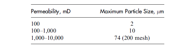
A drilling fluid containing particles of sizes ranging up to the requisite maximum should be able to effectively bridge the formation and form filter cake. Above 10 D or in fractures, larger particles are required, and most likely the amounts needed to minimize spurt loss will also increase with the size of the opening. Generally, with increasing concentration of bridging particles, bridging occurs faster and spurt loss declines. For consolidated rock with permeability in the range 100 to 1000 mD, only
1 lb/bbl of 10-mm particles is necessary to prevent mud spurt from invading farther than 1 inch into the rock. On unconsolidated sands of that same permeability, 5 to 30 times that amount may be required. Reservoir drilling fluids typically contain as much as 30 lb/bbl total of acid-soluble bridging materials (usually CaCO3), sized to provide a broad size distribution for all solids in the fluid.
For nonreservoir applications, enough particles of the required size range are usually present in most drilling fluids after cutting just a few feet of rock. However,extensive use of desanders and desilters when drilling unconsolidated sands may deplete these particles, and some bridging material may have to be added back. Likewise, when no drilling is involved (e.g., production repair jobs), bridging particles will need to be added to the fluid.
4.Rate of Penetration
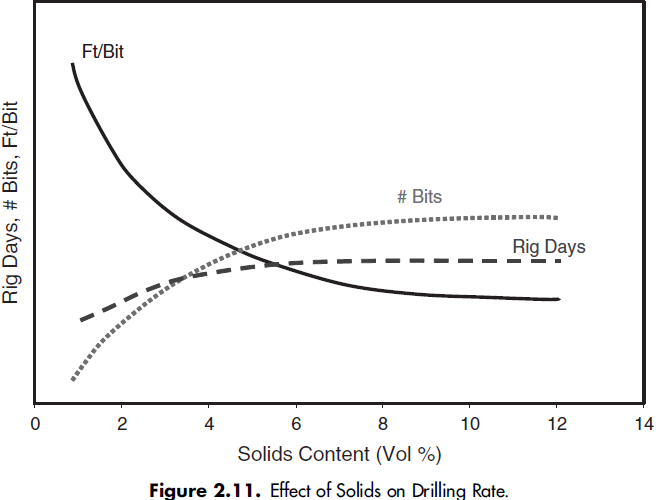
With higher ROP, both rig time and cost of bits are greatly reduced, and the total drilling operation is less costly, as shown in Figure 2.11.
Drilling-fluid parameters that can affect ROP include:
. Density
. Solids content/solids control
. Filtration
. Rheological profile
. Coefficient of friction/lubricity
. Shale inhibition
Generally, any process that leaves only the desirable solids, lubricants, and rheology modifiers in a drilling fluid will enhance ROP.
Density
The most important mud property affecting ROP is density. ROP decreases as the pressure differential (well-bore pressure minus pore pressure) across the rock face increases. Accordingly, a drilling fluid should be as light as possible while still able to maintain well-bore stability. For a given fluid density, use of weighting materials with a high SG (e.g., hematite or ilmenite instead of barite) can increase ROP,because the volume of solids required to generate that fluid density is less and high-shear-rate viscosity is lower. If well-bore stability is not a factor, a gaseous fluid or one containing entrained gas should be considered first, followed by fluids containing hollow crush-proof beads, then oil or emulsion fluids, followed by invert-emulsion muds, freshwater muds, and brines. On the other hand, special equipment is required to drill with gases or gaseous fluids, and safety risks increase with increasing pore pressure of the formation (see Chapter 19 on Underbalanced Drilling).
Solids Content
The relationship between solids content and drilling rate has been known for many years. Broadly speaking, a low concentration of solids leads to a high ROP, as shown in Figure 2.11. The effect is most pronounced with low-solids drilling fluids, such as clear brine fluids and low-solids nondispersed muds. PSD also affects ROP, indirectly. A wide distribution of particle sizes is required to achieve adequate filtration control, which is necessary for most drilling operations. However, if the concentration of noncolloidal drilled solids can be kept below 4% by weight, ROP can be maintained at a high level [Darley]. When these particles are at such a low concentration, they are not able to form an internal filter cake below the chip (cutting) between successive tooth or cutter strikes, that is, the spurt loss is high, and the pressure differential across the chip remains high (see the following section).
Colloidal solids, which fill the interstices of a filter cake formed by the noncolloidal particles, also reduce ROP, but in a different way. With increasing fraction or total concentration of colloidal solids, the external filter cake on a chip forms more quickly and is less permeable, again reducing the probability of being able to form an internal filter cake. The result is that ROP decreases as dynamic fluid loss decreases (more on this in the following section). For clear-brine polymer drilling fluids, very
high ROP is achievable only by removing essentially all of the drilled solids. If a clear brine is infused with enough fine solids to be opaque, ROP will decrease by more than 50%. Nevertheless, in hard rock formations, desanders/desilters or mud cleaners may be able to keep the brine clear, but it is unlikely in younger formations.
Both concentration and PSD of solids also affect the performance of solids-control equipment. For optimal removal of cuttings at the shakers, controlled drilling—limiting the ROP—may be necessary so as not to exceed the operating limits of the pumps and shakers.
Filtration
Historically, the significant reduction in ROP observed during displacing of clear water with clay-based drilling fluid was attributed to chip hold-down pressure (CHDP) [Garnier & van Lingen]. As a tooth from a tricone bit creates a crack in a rock, a vacuum is created under the chip (cutting) unless enough liquid can rush in to fill this incipient crack. Better penetration of the fluid into this crack reduces the pressure drop holding the chip in place, thus facilitating its removal and enabling the
tooth to engage fresh rock. For a permeable formation, the fluid to fill the crack can come from within the formation; this is one of the reasons that sandstones generally drill faster than shales. A somewhat different scenario is postulated for PDC bits. Here the argument is that the differential pressure acting across the chip opposes its initial dislodgement.
In keeping with CHDP theory, several years of study indicate that ROP increases as density decreases and filtration control is relaxed, regardless of the type of bit. However, ROP does not appear to correlate with static fluid loss, such as is measured with the API Fluid Loss Test. On the other hand, ROP appears to correlate very well with dynamic fluid loss. These are tests designed to simulate downhole flow of fluid across the face of the filter cake, leading to continual erosion and production of a constant thickness cake. Thus, as dynamic fluid loss increases, so does ROP. It is essential in these tests to use core from the area to be drilled.
As might be expected on the basis of CHDP, if the rock being drilled has very low permeability (in the extreme case, shales with no microfractures), dynamic fluid loss measurements will show very low fluid loss, and consequently ROP will be lower than in permeable rock.
Rheological
Fluids with low viscosity at high shear rates effectively overcome the chip hold-down effect and sweep the hole clean of drilled solids quickly, thereby minimizing regrinding. Often, though not necessarily, PV is also low; the relevant viscosity, however, is the viscosity under the bit, that is, the Fann Reading at high Fann Speed. Generally a formation drills faster the more shear-thinning and flatter the rheological profile of the mud. This again reinforces the advantages of a ‘‘clean’’ drilling fluid.
Lubricity
The ability to turn the drill string, log the well, and run casing in highly convoluted well bores is considered desirable. High lubricity (low coefficient of friction) of the drilling fluid, whether attained mechanically with the addition of glass or polystyrene beads or chemically with the addition of oils or surfactants, enables more accurate control of weighton-bit and drill string rotation, thereby enhancing ROP.
Shale Inhibition
‘‘Balling’’ occurs when drilled cuttings are not removed from beneath the bit and they collect between the bit and the true hole bottom (bottom balling) or in the cutters or teeth of the drill bit (bit balling). This effect is most pronounced with hydratable shales (e.g., gumbo) in WBMs. Static and dynamic CHDP conspire with the hydrational and adhesive forces to make the cuttings very soft and sticky. This effect can be reduced by making the mud either more inhibitive or less inhibitive so as to reduce the hydrational and adhesive forces. More on this may be found in the following section.
5.Shale Inhibition Potential/Wetting Characteristics
Because the continuous phase in NAFs is nonaqueous, cuttings drilled with NAFs do not hydrate, and they are left oil wet and nearly intact. Invert-emulsion NAFs can actually increase cuttings’ hardness by osmotically removing water from the cuttings. WBMs, on the other hand, generally are not very efficient at removing water from the cuttings; indeed they may only slow hydration, so that cuttings will still tend to imbibe water, swell, soften, and even disperse. The same phenomenon occurs in the well bore, so that both well-bore stability and cuttings integrity suffer with increased residence time of the mud downhole.
Highly inhibitive WBMs, such as PHPA/glycol in a 20 to 25% solution of NaCl, can remove water from the cuttings, but the cuttings may actually get stickier, depending on how wet they were when generated. The Atterberg limits give a qualitative picture of the effect of removal or imbibition of water on plasticity, or stickiness, of cuttings [Bowles], which may promote bit balling (see Fig. 2.12). Shale-laden cuttings from young formations, such as gumbo-like argillaceous formations of the Gulf of Mexico, tend to be very wet and on the downslope right side of the Atterberg curve. Exposure to highly inhibitive WBMs may remove some, but not enough, water and cause the shale to travel left back up the curve to a more sticky condition. Cuttings generated using this kind of mud tend to be stickier than those generated with a less inhibitive mud [Friedheim et al.], so that blinding of shaker screens is a common occurrence. Replacing the fluid with NAF can remedy this problem, but treatment of the WBM with a drilling enhancer (or ROP enhancer) may be more economical. Although WBM treated with a drilling enhancer presents more risk than NAF, it can reduce bitballing tendency significantly, as well as blinding of screens and other solids-control problems. Most drilling enhancers possess the added virtue of imparting additional lubricity to the fluid and reducing abrasiveness of the cuttings.

A drilling-fluid coefficient of friction that is low (0.1 or less) is generally advantageous, inasmuch as it helps the cuttings to travel as discrete particles over shaker screens. Most mud lubricants will also tend to adsorb onto almost any surface, including the exposed surfaces of the solids-control equipment. A thin film or coating of mud lubricant on those surfaces can help to protect them from corrosion and mitigate adhesion of sticky solids.
7.Corrosivity
To minimize corrosion of steel tubulars and solids-control devices, control of the responsible agents is a necessity. NAFs effectively prevent corrosion because they are nonconductive and oil-wet the steel surfaces. WBMs, on the other hand, can contain dissolved materials that set up electrochemical cells that ultimately lead to loss of iron from the steel surfaces in contact with the drilling fluid [Bush]. Dissolved O2 forms rust and pits on the steel surface, and is best controlled by minimizing air
entrainment: use only submerged guns in the mud pits; rig all return lines from desanders, etc., to discharge below mud level; and minimize use of the hopper. Keeping the mud at a pH between 9 and 10—with Ca(OH)2 (lime), NaOH (caustic), or MgO—helps greatly to keep the rate of corrosion at an acceptable level. A higher pH is not recommended, particularly in high-temperature wells, because under those conditions the hydroxyl ion becomes very reactive toward clays and polymers. If too
much corrosion still occurs, O2 scavengers such as sodium sulfate (Na2SO3) and triazine can be very effective. Less common but also very effective are corrosion inhibitors, such as amines and amine salts, which produce an oily barrier to O2. The other two primary agents of corrosion are carbon dioxide (CO2) and hydrogen sulfide (H2S). Both of these form acids in aqueous drilling fluids. H2S in particular is a cause for concern because of its high toxicity and its ability to cause hydrogen stress cracking that can lead to fatigue failure of tubulars and solids-control equipment. Again, a high pH can serve as the front line of defense. For high levels of H2S, though, zinc carbonate, zinc chelate, powdered iron, or magnetite may also be necessary. A mixture recommended by the API for polymer-based WBMs to minimize both corrosion and degradation of polymers by O2, CO2, and H2S consists of MgO, Na2SO3 or triazine, and triethanolamine (to sequester iron and remove H2S/CO2) [API RP 13C].
It should be noted that dissolved CO2, O2, and salts can all accelerate stress cracking and failure of steel hardware, though the effect is most pronounced with H2S.
Finally, microbes can form corrosive agents, particularly H2S, via degradation of mud components in the drilling fluid like lignosulfonate or biopolymers. The most effective ways to control microbial corrosion are through use of clean make-up water and a biocide, such as glutaraldehyde or bleach.
8.Drilling-Fluid Stability and Maintenance
Maintaining the drilling fluid in good condition is essential not only for controlling the mud properties but also to ensure proper operation of solids-control equipment. Vigilance against the effects of contamination and elevated temperatures is particularly important. Invasion of foreign materials, such as water and oils, and thermal degradation of polymers can affect viscosity and filtration properties radically and compromise the performance of some solids-control equipment. Elevated temperatures can also destroy direct and invert-emulsion systems and can cause gelation in clay-based muds, either of which can negatively affect equipment performance. Keeping the mud properties within the design parameters is critical, which requires maintaining the concentrations of mud products and drilled solids at appropriate levels.