

The majority of shale shakers use a back tank (commonly known as a possum belly or a mud box) to receive drilling fluid from the flowline (Figure 7.3). Drilling fluid flows over a weir and is evenly distributed to the screening surface, or deck. The screen(s) are mounted in a basket that vibrates to assist the throughput of drilling fluid and the movement of separated solids. The basket rests on vibration isolator members, such as helical springs, air springs, or rubber float mounts. The vibration isolation members are supported by the skid. Below the basket, a collection pan (or bed) is used to channel the screen underflow to the active system.

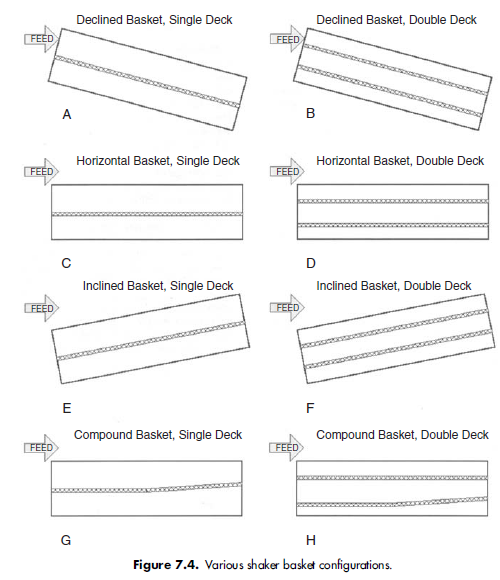
Shale shaker performance is affected by the type of motion, stroke length of the deck, and the rotary speed of the motor. The shape and axial direction of the vibration motion along the deck is controlled by the position of the vibrator(s) in relation to the deck and rotation direction of the vibrator(s). There are many commercially available basket and deck configurations. The deck may be mounted at a slope (Figures 7.4A, B, E, and F) or horizontally (Figures 7.4C and 7.4D). Deck surfaces may be tilted up or down in the basket. The basket may be horizontal or at a fixed angle, or have an adjustable angle. An adjustable basket angle allows the deck to be tilted up or down.
On sloped deck units (cascade or parallel flow), the screens may be continuous, with one screen covering the entire deck length (Figures 7.4A and E), may have a divided deck that has more than one screen used to cover the screening surface (Figures 7.4B and F), or may have individual screens mounted at different slopes (Figures 7.4G and H). On multiple deck units, fluid passes through the upper deck before flowing to the next deck (Figures 7.4B, F, and H).

One Reply to “shale shaker description”
Comments are closed.