

Vacuum Degasser Design Concept Formulation
The new Vacuum Degasser design was formulated from basic principles used in the chemical processing industry. Standard chemical engineering principles that apply to the design of packed towers were the basis for this new design. These principles deal with efficient phase disengagement to provide’ effective gas absorption or gas strip-ping. Specifically, in the top inlet section of a typical packed tower, the overriding operating principles are effective gas/liquid phase disengagement and uniform inlet liquid distribution over the entire tower cross-sectional area.

Proper packed-tower design requires prevention of entrainment of liquid droplets in the exiting gas stream. To accomplish this, the tower diameter must be such that the superficial liquid mass flow rate does not exceed certain defined operating limits. This parameter is defined in Eq. 1 in terms of the inlet liquid flow rate, liquid density, and tower cross sectional area.
![]()

While the tower diameter must be designed to process the maximum expected liquid flow rate, it must also be de” signed to handle the maximum expected gas flow rate. The superficial gas’ mass flow rate is also critical to the tower diameter selected and is defined in Eq. 2 in terms
of the gas flow rate, gas density, and tower cross-sectional area.
![]()

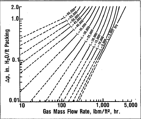
Together these two parameters form a relationship that allows an estimation of the pressure drop resulting from the countercurrent passage of falling liquid and rising gas within the tower packing. If this pressure drop is excessive in the packed section (more than 2 in. H2 0/ft [1.63 kPa/m] of packing), tower flooding occurs, which prevents passage of gas through the liquid-filled, packed section. Packed-tower pressure drop is a function of superficial gas and liquid mass flow rates and is expressed
in the empirical Leva equation.


This equation is based on experimental data obtained from packed towers under preloading conditions where pressure drop is low and is a linear function of gas and liquid mass flow rates. Although the Leva equation is useful for an estimation of the packed-tower pressure drop, we decided that the use of pressure-drop curves available from the packing manufacturer would provide a more accurate estimation of pressure drop that would occur in the vacuum degasser unit. The decision to use the packing manufacturer’s pressure-drop chart was based on four assessments:
- The Leva equation is only a tool for estimating pressure drop.
- The equation cannot accurately estimate pressure drops in the loading region of 1 to 2 in. H2 0/ft [816 to 1634 Palm] of packing.
- Packing constants for the packing type and size chosen were not readily available for use in the Leva equation; and
- Pressure-drop curves were available to predict pressure drop accurately for almost any liquid or gas rate required.
Tower diameter selection is usually made with the maximum expected gas and liquid flow rates and depends on the size and type of tower packing. The portion of Fig. 3 with solid lines illustrates the pressure-drop relationship fQf l.5-in. [3 .81-cm] Pall rings supplied by the manufacturer
for typical superficial gas and liquid flow rates used in the chemical processing industry. 3 This relationship is usually available in graphical form from any manufacturer of packed-tower packing elements. While these correlations for pressure drop vs. gas and liquid flow-rate correlations are considered the most accurate means of predicting actual operating characteristics of a packed tower, this is true only if similar liquid/gas systems are used and the design operating flow rates appear on the manufacturer’s experiment-based graphs. It was this latter consideration that required another engineering judgment to be made.


The vortex vessel installed in Salt Creek required a gas separator designed for 50,000 BFPD [7950 m3 /d fluid] and at least 150 Mcf/D [4250 m3 /d] of gas. If Eqs. l and 2 are used to calculate the values in Table 1, the calculated superficial gas mass flow rates fall to the left of the data provided by the packing manufacturer in Fig. 3. Because in Fig, 3, pressure drop is considered a linear function. of gas and liquid mass flow rates in the preloading region where pressure drop is low, I these lines can be extrapolated without introducing significant error. The dashed lines in Fig. 3 are the result of this assumption and were used in the design of the optimum degasser diameter. Table 2 presents the actual values used to determine the first degasser diameter. Because of the uncertainty of operation of this new design and of the ac-tual gas rates to be encountered in the very first installation, the 6-ft [1. 83 m] -diameter size was selected even though a 5-ft [1.52 m] -diameter unit should have provided adequate separation.

The preceding discussion of the degasser unit design has focused on its similarity to a packed tower. While this would be true if the liquid were introduced into the top of the tower and the gas into the bottom, it is not entirely true for the degasser unit design. The unique aspect of this degasser unit is that both the liquid and gas are introduced into the top of the unit.
This new design is presented in Fig. 4. The inlet fluid distributor provides even liquid distribution onto the packing section and gives the inlet gas and liquid a downward velocity. Downward velocity reduces liquid entrainment in the existing gas stream because the gas must reverse
direction from that of the liquid to exit through the upper gas outlet. Gas exits the top of the unit because its density is much lower than that of oil and water. Liquid, because of its higher density, continues to fall downward by gravity onto and through the packing to exit through the bottom liquid outlet.
In addition to separating the volumes Of gas from the liquid immediately before they enter the packing, this design allows some solution gas to separate from the liquid as it falls through the packing. The packing used in this degasser has a surface area of 40 ft²/ft³[131 m²/m³ ] of packing and represents a vastly larger surface area for effective solution gas removal than conventionally designed separators with no packing. The small amount of solution gas evolving from the liquid in the packing also serves to strip even more gas from the liquid. Although the solution-gas volume removed in this manner may be small, it does prevent the gas from evolving from the oil in the production battery stock tanks. Gas evolving inside these bolted tanks represents an economic loss if vapor recovery is desired because some loss of vent gas through the bolted deck seams is inherent in the operation of bolted steel tanks. This loss has been observed even when care has been taken to use good-quality rubber seal gaskets and thief hatch seals.

This degasser design is sized to operate as though all the inlet gas enters through the bottom of the unit because no simple design equations exist for this type of packedcolumn operation. Therefore, the designed diameter becomes a significant overdesign factor. This may seem to make the diameter much larger than required, but remember that the surging of the inlet fluid introduces instantaneous rates of up to five times the average. These undesirable inlet conditions necessitate the small cost increase
of oversizing the degasser diameter.
Degasser Construction
Considerations for materials of construction were cost, resistance to corrosion, and weight. Because the initial design pressure rating for this separator was 5 psig [34.5 kPa], the material selected was fiberglass. This first unit was constructed of a polyvinyl ester resin laminated with woven and chopped fiberglass. This unit cost $5,050 complete with the packing and is very resistant to corrosion because of the fiberglass construction. Corrosion resistance is a requirement in Salt Creek because produced
water contains dissolved hydrogen sulfide (H 2 S). Associated vent gas is also sour, with up to 1% H2 S. The unit must be lightweight because of the required elevated installation position 24 to 32 ft [7.3 to 9.8 m] above ground. Stability of such an elevated degasser again made fiberglass a preferable material choice.


Other design details for this degasser include the sizing of the fluid inlet piping diameter, the diameter of the inlet fluid distributor, the gas outlet piping diameter, and the liquid outlet and pipe support diameter. Fig. 5 illustrates the installation piping configuration of the vacuum degasser unit with respect to the vortex vessel. The fluid inlet piping diameter was designed to be 12 in. [30.5 cm] on the basis of field experience and the anticipated flow rates of 50,000 BFPD [7950 m³ /d fluid] and 150 Mcf/D [4250 m³ /d] of associated gas. The inlet liquid distributor was sized to be 12 in. [30.5 cm] with four 8-in. [20.3-cm] cross pipes. These pipes were drilled with numerous 1-in. [2.5-cm] holes to distribute liquid uniformly onto the packed section. The gas outlet diameter was designed to be 6 in. [15.2 cm] to minimize pressure drop as vent gas flows to the flare stack. The liquid outlet piping was designed to be 16 in. [40.6 cm] to provide stability and support for the elevated degasser unit and to minimize the pressure drop that liquid incurs while entering the vortex vessel. This pressure drop could not exceed
2 ft H20 [6.0 kPa] without requiring elevation of the degasser above the top edge of the vortex tank. If the outlet liquid pressure drop exceeds the hydrostatic head available from the bottom of the degasser packing to the
upper oil level in the vortex vessel, the outlet liquid level would rise into the packed section and could cause the degasser to flood. Although this latter design factor of outlet piping diameter is important for pressure-drop considerations, the design diameter was restricted to 16 in.
[40.6 em] or larger because of the need for adequate degasser support and stability in its elevated position in high-velocity Wyoming winds.
Eq. 4 is the Hazen-Williams equation for water pressure drop in pipes and is very reliable in predicting pressure losses in water flowlines in the Salt Creek field.


The Hazen-Williams equation can be used for pressure drop calculation only after friction losses in pipe fittings and valves are converted into equivalent pipe lengths. Consulting any piping hydraulic data book (see Ref. 5) and Fig. 5 will result in a table of values similar to Table 3.. Although this technique provides only approximate pipe lengths, it does give the engineer a target v’alue to which he should apply overdesign allowances. Application of Eq. 4 to the total equivalent length in Table 3 of 185 ft [56.4 m] yields a pressure drop of 0.52 ft H2O [1.55 kPa] for standard 16-in. [40.6-cm] pipe at a liquid flow rate of 50,000 BFPD [7950 m3 /d fluid]. Because this value is less than 2 ft H2O [6.0 kPa], the degasser does not need to be elevated above ‘the position indicated in
Fig. 5.


Table 4 provides an easy reference for degasser height requirements at or above the level indicated in Fig. 5. Where calculations give height values of less than 2 ft H2O [6.0 kPa], the minimum of 2 ft [0.6 m] is indicated.
Standard 16- and 20-in. [40.6- and 50.8-cm] steel piping ID’s were used for pressure-drop calculations. Here it can be seen that a design change to 20-in. [50.8-cm] steel pipe for outlet pipe diameter at liquid flow rates of
125,000 BFPD [19 875 m3 /d fluid] or higher will allow degasser installations to be kept at the same height without anticipation of any flooding problems.
Initial Vacuum Degasser Operation
Once the flume separator and piping shown in Fig. 1 were removed and the new degasser unit and piping were installed (as in Fig. 5), the performance characteristics of the Vortex Treating System immediately improved. Circular motion of the fluid within the vortex vessel was greater; we saw no evidence of gas boiling through the upper oil layer; and the vessel’s pressure limit was no longer being exceeded. Oil quality in terms of sediment and water (S&W) improved substantially in that the
amount of entrained water immediately fell from 12% to an average of about 0.15 %. This oil quality is well with~ in the pipeline specification of 0.3% S&W, and this was the first time such excellent oil quality had been achieved in any gunbarrel or other production treating system in Salt Creek. Another aspect of improved degasser performance was an obvious increase in the vent-gas rate coming from the degasser unit compared with the flume separator operation. Although the gas rates were not measured at the time, this empirical method was additional evidence of the degasser’s efficient gas separation capabilities.
Operational Problems and Their Solutions
Operational difficulties with any new equipment design in the oil field are to be expected. This new degasser design was no exception. Proj)lems encountered were easily remedied at little cost and have improved the degasser’s overall long-term reliability and efficiency .
The first problem encountered after about 6 months of operation was plugging of the inlet liquid distributor with large pieces of calcium carbonate scale. Although this was more a fluid quality problem than a degasser problem, it still required correction upstream of the degasser. This scale formation can be prevented in the long term by scale inhibition, but it also required a short-term solution. Inspection of this scale debris indicated that it had come from the production flowlines leading to the production battery. This seemed reasonable because a large amount of flowline construction work had been done in the area for a recent waterflood expansion.
This flowline work can dislodge scale buildup and allow it to break up and flow downstream toward the production battery. Later, this same problem also occurred in other degasser units in the field following flowline construction work.
The first evident symptom was a substantial rise in the oil and grease levels in the vortex discharge water. Presumably, this was the result of emulsion formation in the plugged distributor caused by excessive turbulence as the fluid flowed through the scale debris. This turbulence
and restriction to normal flow made the second symptom evident: higher inlet fluid pressure. Cleaning of the fluid distributor resulted in an immediate drop in the inlet fluid pressure aQd a drop in the oil and grease levels in the vortex discharge water to their previous levels. The solution to this problem was the installation of a Y-strainer unit In the upstream piping to catch the debris. With this simple addition, scale debris can now be periodically flushed to the production water settling ponds with no degasser plugging.
The second problem encountered was loss of packing through the liquid outlet piping, which resulted from substantial movement of the packing supports with only two possible causes: flooding of the degasser unit and overpressure of the degasser, resultit;lg in swelling of the fiberglass unit. Flooding was by far the most plausible cause because most of the units with lost packing were those that had been installed with insufficient degasser elevation above the liquid level in the vortex tank. In these units, inlet fluid rates had exceeded the maximum design and therefore required unit elevation. In other installations, inadvertent closure of the vent-gas valve resulted in severe overpressure of the units and obvious flexing and swelling until the valve was reopened. Because of this, some units cracked and required repair. It is this swelling that allowed movement of the vacuum degasser walls away from the packing supports and allowed packing elements to escape. Possible solutions to this problem were removal of the vent-gas valves, installation of relief valves, or an increase in the fiberglass thickness in the degasser walls to take the higher pressure. Because of other operating considerations, increasing the thickness was chosen, which led to an increase in the fiberglass degasser rating to 25 psig [172 kPa] from the original 5-psig [34-kPa] rating.
Current Operations
Since the initial degasser installation in late 1982, 11 other units have been constructed of fiberglass and put into service with new Vortex Treating Systems. These units involve three different oil fields in Wyoming and have operated for up to 3 years. The diameters of these 11 units range from 4 to 10 ft [1.2 to 3 m], with a wide range of liquid flow rates evident with a fairly narrow range of associated gas flow rates. This is to be expected because oil fields with production fluids containing larger volumes of gas have two-phase separators or free-water knockouts in line upstream of the production batteries. In this manner, the majority of produced gas can be recovered at a higher pressure, thus saving compression costs.
Because efficient separation of gas is the primary purpose of the vacuum degasser, it was rewarding to confirm that more gas was being recovered from each production battery than before the installation of the vortex system. This gas flow-rate information was obtained after installation of large-capacity 10w-pressure-drop gas turbine meters. Earlier gas measurements were taken with similar gas turbine meters but showed substantially less gas flowing to the flare stacks. Installation of a separate vent line for the degasser unit to its own flare stack revealed that nearly all the vent gas produced at the battery was being recpvered in the degasser. This information made any vapor recovery project for the Salt Creek field more attractive because of the larger-than-expected recovera~le gas flow rates.
This degasser design has proved to be a very efficient separator in terms of liquid and gas capacity for a very reasonable cost. This design has allowed the Vortex Treating System to operate beyond original expectations as a primary oil/water separation system. Through continued operation, it is hoped that this degasser design will be tested as an in-line two-phase separator.
Conclusions
- This degasser design is more efficient in gas separation and liquid desurging than the flume-type separator when used with the Vortex Treating System in primary oil/water separation.
- This vacuum degasser unit is superior to most two-phase separators on the market in terms of stated liquid and gas separation capacity as a function of size and cost.
- This design has made possible the construction and effective operation of Vortex production batteries in the Salt Creek field.
- Efficient operation of this two-phase· separator design has increased the volume of recoverable production battery vent gas in the Salt Creek field.
- Significant operational problems with this degasser resulted from operating the unit beyond its pressure rating and below the height requirements stated for adequate operation. Therefore, it is imperative that the ancillary piping for the degasser, as well as the degasser itself, be
properly engineered for the flow and pressure conditions that may be encountered. - Degasser plugging can be prevented by installation of an in-line strainer unit upstream of the degasser unit.
- Application of this degasser design to in-line twophase separation should.be considered, judging from effective operation with Vortex Treating Systems.
