

The minimum volume required to dilute solids remaining after processing by the solids-control equipment depends on the drilled solids concentration in the drilling fluid. If all of the drilled solids are removed from the system, the clean drilling fluid added to return the pit levels back to the original level will dilute the solids already in the drilling fluid. As noted earlier, more clean drilling fluid will be needed to return the pits to the original level with 100% removal than 90% removal of drilled solids.

TANK ARRANGEMENT-2
1.5 Equalization
Most compartments should have an equalizing line, or opening, at the bottom. Only the first compartment, if it is used as a settling pit (sand trap), and the degasser suction tank (typically the second compartment) should have a high overflow (weir) to the compartment downstream.
The size of the equalizing pipes can be determined by the following formula:
Pipe diameter=√Max. Circulation Rate; gpm/15
A pipe of larger diameter can be used, since solids will settle and fill the pipe until the flow velocity in the pipe is adequate to prevent additional settling (5 ft/sec).
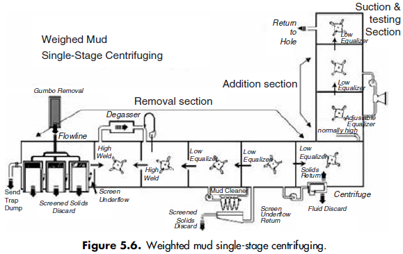
An adjustable equalizer is preferred between the solids-removal and additions sections. The lower end of an L-shaped, adjustable equalizer, usually field fabricated from 13-inch casing, is connected to the bottom of the last compartment in the removal section. The upper end discharges fluid into the additions section and can be moved up or down. This controls the liquid level in the removal section and still permits most of the fluid in the suction section to be used.
1.6 Surface tank
Most steel pits for drilling fluid are square or rectangular with flat bottoms. Each tank should have adequate agitation except for settling tanks. Additionally, each tank should have enough surface area to allow entrained air to leave the drilling fluid. A rule of thumb for calculating the minimum active surface pit area is:
Area, ft^2=Flow rate (gpm)/40
For example, if the active circulating rate is 650 gpm, the surface area of each active compartment should be about 16 square feet. The depth of a tank is a function of the volume needed and ease of stirring. Tanks that are roughly cubical are most efficient for stirring. If this is not convenient, the depth should be greater than the length or width. If circular tanks are used, a conical bottom is recommended and centrifugal pump suction and/or a dump valve should be located there. Another consideration is that the tanks need to be deep enough to eliminate the possibility of vortexing at the centrifugal pump suction. The depth required is a function of the velocity of the drilling fluid entering the suction lines (Figures 5.3, 5.4, 5.5, and 5.6).


1.7 Sand trap
After the drilling fluid passes through the main shaker, it enters the mud pit system. When screens 80-mesh and coarser were routinely used, the sand trap performed a very useful function. Large, sand-size particles would settle and could be dumped overboard. The bottom of a sand trap should be sloped at about 45° to facilitate quick dumping. A sloped bottom 45° or greater will self-clean when dumped. The sand trap should not be agitated and should overflow into the next compartment. Linear
and unbalanced elliptical motion shale shakers have all but eliminated this technique. Small drilled solids generally do not have sufficient residence time to settle. When inexpensive drilling fluid was used, sand traps were dumped once or twice per hour. Today, in the era of fine-mesh screens,expensive waste disposal, and environmental concerns, such dumping is either not allowed or is cost prohibitive.
The preceding illustrations show the solids-removal system with a sand trap. Rigs currently operating may or may not have sand traps. If a rig does not have a sand trap, then the shakers would have their underflow directed to the degasser suction pit and all other functions would remain as illustrated.
1.8 Degasser suction and discharge pit
For proper operation of a vacuum-type degasser, the suction pit should be the first pit after the sand trap, or if no sand trap is present, then the first pit. This pit should typically be agitated in order to help roll the drilling fluid and break out as much gas, if present, as possible. The processed fluid flows into the next pit downstream. There needs to be a high equalizer or weir between these two tanks.
The degasser discharge pit is also the suction pit for the centrifugal pump used to pump drilling fluid through the eductor on the degasser. This is commonly called power mud. Pumping power mud through the eductor actually pulls the fluid out of the degasser vessel from the degasser suction pit and out to the discharge line due to the Bernoulli effect, causing a low-pressure zone in the eductor. The discharge from the eductor goes back into the same tank used for the suction for the power mud.
The reason that mud is sucked into the vacuum degasser and through the degasser vessel is that a centrifugal pump will not pump gaseous mud; therefore it cannot be pumped through the vessel and has to be sucked into it. (For complete information on operation of degassers, refer to Chapter 9 (Gas Busters, Separators, and Degassers) in this book.)
1.9 Desander suction and discharge pit
The degasser discharge pit is also the suction pit for the desander. The desander, as well as the desilter, needs to be downstream of the degasser operation. If the hydrocyclone suction is upstream of the degasser operation and gas is present in the mud, the efficiency of the centrifugal pump will be reduced, or the pump will become gas locked and simply not pump any mud. Additionally, induced cavitation can occur and cause premature wear to the centrifugal pump. This wear can be rapid
and severe.
The desander discharge (cone overs) should flow into the next pit downstream, and a low equalizer between these tanks should be opened. This allows backflow through the equalizer when the cone manifold is processing a greater volume than is entering the tank (recommended). This ensures that all of the drilling fluid is processed through the desander manifold.
Desander operation is typically recommended only for unweighted drilling fluids. If operated with weighted drilling fluid, the desander will discard a lot of drilling fluid away, including a lot of weight material.
1.10 Desilter suction and discharge pit (mud cleaner /conditioner)
The desilter suction pit is the desander discharge pit. The desilter will remove smaller particles than the desander, so its operation is downstream of the desander. Setup and operation of desilters are the same as with desanders. The manifold discharge is downstream of the suction, with a low equalizer between the two tanks. It is recommended that the desilter process more volume than the rig is pumping so that there is a backflow through the equalizer, ensuring that all of the drilling fluid is
processed.
If drilling fluid is being pumped through mud guns from the suction compartment downstream, this fluid must also be processed through the hydrocyclones. For weighted drilling fluids, the underflow of the desilter cones is processed by a shaker. Ideally this shaker will have screens installed that allow the weight material to pass through while rejecting any drilled solids larger than the weight material.
1.11 Centrifuge suction and discharge pit
Centrifuge suction is taken from the pit that the desilter manifold discharges into (for unweighted drilling fluids). The drilled solids removed by the centrifuge are discarded, and the cleaned drilling fluid is returned to the active system in the next pit downstream.
For a weighted aqueous drilling fluid, the solids separated by a centrifuge are composed largely of weight material (assuming upsteam processing has been performed correctly) used to increase the density of the drilling. This solids discharge (centrate or cake) is returned to the active system and the effluent or liquid discharge is discarded. The effluent contains the fine particles (colloidal or clay size) that will cause rheological problems with the drilling fluid if allowed to accumulate to a
high enough concentration.
For a weighted nonaqueous drilling fluid, it is not feasible to discharge the effluent from a centrifuge, due to environmental and/or economic concerns. In this situation, a dual centrifuge setup is utilized in which the first centrifuge operates at a lower g setting (usually 600–900 g) and the weight material (which is easy to separate due to its higher specific gravity) is returned to the active system. The effluent from the first centrifuge typically flows to a holding tank, and this fluid is not processed by a second centrifuge operating at a higher g force in order to separate finer solids, which are discarded. The solids from the second centrifuge typically are not in the size range that would cause rheological problems, but given time they will degrade into smaller particles that could start causing problems. Therefore, they need to be removed while the equipment can still remove them. The effluent from the second centrifuge is then returned to the active system.