One of the international benchmarks for an efficient solids control and waste management system is to incorporate a Centrifugal Cuttings Dryer (VCD) into any environmental management strategy. The VCD (Vertical cuttings dryer) units typically consist of a high-speed vertical centrifuge that achieves maximum liquid solid separation in large volume processing.
The most common power source for shale shakers is the rig electrical power generator system. The rig power supply should provide constant voltage and frequency to all electrical components on the rig. Most drilling rigs generate 460 alternating-current-volt (VAC), 60 Hz, 3-phase power or 380 VAC, 50 Hz, 3-phase power. Other common voltages are 230 VAC, 190 VAC, and 575 VAC. Through transformers and other controls, a single power source can supply a variety of electrical power to match the requirements of different rig components. Shale shakers should be provided with motors and starters to match the rig generator output. Most motors are dual wound. These may be wired to use either of two voltages and starter configurations. For example, some use 230/460VAC motors and some use 190/380VAC motors. Dual-wound motors allow the shaker to be operated properly with either power supply after relatively simple rewiring. Care must be taken, however, to make certain that the proper voltage is used. Electric-motor armatures are designed to rotate at a specific speed. Typically the rotational speed is 1800 rpm for 60-Hz applications and 1500 rpm for 50-Hz applications.
Shale shakers use a vibrating screen surface to conserve the drilling fluid and reject drilled solids. The effects of this vibration are described in terms of the g factor, or the function of the angular displacement of a screen surface and the square of the rotational speed. (For a detailed discussion, see the preceding section on g factor.)
Angular displacement is achieved by rotating an eccentric mass. Most shale shakers are designed to be operated at a specific, fixed g factor by matching the stroke to a given machine’s rotational speed. It follows that any deviation in speed will affect the g factor and influence the shaker performance.
Deviations in speed may be caused by one or more factors but typically are caused by fluctuations in voltage or the frequency of the alternating current. If the voltage drops, the motor cannot produce the rated horsepower and may not be able to sustain the velocity needed to keep the eccentric mass moving correctly. Low voltage also reduces the life of electrical components. Deviations in frequency result in the motor turning faster (frequencies higher than normal) or slower (frequencies lower than
normal). This directly influences rpm and shaker performance.
Slower rpm for a particular motor reduces the g factor and causes poor separation and poor conveyance. Faster rpm increases the g factor and may improve conveyance and separation, but can destroy the machine and increases screen fatigue failures. In extreme cases, higher rpm may cause structural damage to the shale shaker. Thus, it is important to provide proper power to the shale shaker.
For example, a particular shale shaker is designed to operate at 4 g’s. The shaker has an angular displacement, or stroke, of 0.09 inches. This shaker must vibrate at 1750 rpm to produce 4.1 g’s. At 60 Hz, the motor turns at 1750 rpm, so the g factor is 4.1, just as designed. If the frequency drops to 55 Hz, the motor speed reduces to 1650 rpm, which results in a g factor of 3.5. Further reduction of frequency to 50 Hz results in 1500 rpm and a g factor of 2.9.
Most rigs provide 460 VAC, 60 Hz power, so most shale shakers are designed to operate with this power supply. However, many drilling rigs are designed for 380- VAC/50-Hz electrical systems. To provide proper g factors for 50-Hz operations, shale shaker manufacturers rely on one of two methods: increasing stroke length or using voltage/ frequency inverters (transformers).
A motor designed for 50-Hz applications rotates at 1500 rpm. At 0.09-inch stroke, a shale shaker will produce 2.9 g’s. Increasing the stroke length to 0.13 inches provides 4.1 g’s, similar to the original 60-Hz design. However, the longer stroke length and slower speed will produce different solids-separation and conveyance performance. At the longer stroke lengths, shakers will probably convey more solids and have a higher fluid capacity. Conversely, instead of increasing the stroke length, some manufacturers use voltage inverters to provide 460-VAC/60-Hz output power from a 380-VAC/50 Hz supply.
Constant electrical power is necessary for good, constant shale shaker performance. The tables below assist in designing a satisfactory electrical distribution system.
Alternating-current motors are common on most shale shakers. The motor rating indicates the amount of electrical current required to operate the motor. The values in Table 7.1 provide some guidelines for various motors. Be wary of all electrical hazards; follow all applicable regulatory codes, nationally, internationally, regionally, and locally, as well as manufacturer’s safety and installation instructions. The manufacturer’s recommendations should always take precedence over the generalized
values in these tables. The values in the tables are to be used as general guidelines only. Many factors, including insulating material and temperature, control the values.
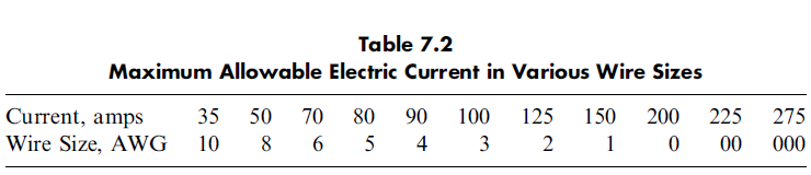
The amount of electric current that a conductor (or wire) can carry increases as the diameter of the wire increases. Common approximate values for currents are presented with the corresponding wire size designation in Table 7.2. Conductors, even relatively large-diameter wire, still have some resistance to the flow of electric current. This resistance to flow results in a line voltage drop. When an electric motor is located in an area remote from the generator, the line voltage drop may decrease
the motor voltage to unacceptably low values. Some guidelines of wire diameter necessary to keep the voltage drop to 3% are presented in Table 7.3.
hp=horsepower; v=volts.
WARNING: Electrical Hazard—follow ALL national electric codes, local electric codes, and
manufacturer’s safety and installation instructions. Always conform to regulatory codes, as
apply regionally and internationally.
AWG=American Wire Gauge.
WARNING: Electrical Hazard—follow ALL national electric codes, local electric codes, and
manufacturer’s safety and installation instructions. Always conform to regulatory codes,
as apply regionally and internationally.
Shale shakers have undergone many improvements since the Shale Shaker Handbook was written in the early 1970s. The current design, linear motion shakers, was introduced in the 1980s and has become widely used because of its improved solids conveyance and fluid throughput. The various types of motions are discussed in the next sections. Linear motion has made it possible to move solids toward the discharge end of the deck while it is tilted uphill. The uphill tilt of the deck creates a pool of fluid at the feed end of the deck, which, in combination with the linear motion, exerts greater pressure on the fluid flowing through the screen openings. This allows a finer screen than with all previous shaker designs. The acceleration perpendicular to the screen surface controls the liquid throughput. Orbital (circular or unbalanced elliptical) and linear motion shakers can have the same acceleration (or g factor), but the linear motion shaker can process a greater flow rate. The linear motion conveys solids uphill, whereas orbital motion will not. The uphill solids conveyance allows the linear motion or balanced elliptical motion to process a greater flow rate.
The use of linear motion shakers has become feasible with the development of improved screen designs. The life of shaker screens has been extended with the introduction of repairable bonded and pretensioned screen panels. Other design improvements are available in wire cloth, rectangular weaves, nonmetallic screens, and three-dimensional screen surfaces, which have improved the solids-separation capabilities of all shakers.
Although linear motion shale shakers have made a significant impact on solids-removal concepts, the other shale shakers have many advantageous features. Circular motion is easier on the shale shaker structure and shaker screens and conveys gumbo better than does linear motion. Linear motion shakers require bonded screens of which 30–50% of the area is forfeited. The liquid pool at the back of the linear motion screens can cause solids to be ground up into many smaller particles and forced through the shaker screens. This liquid pool also gives solids slightly finer than the screen openings more of a chance to go through the screen.
A shale shaker’s capacity has been reached when excessive amounts of drilling fluid (or drilling-fluid liquid phase) first begins discharging over the end of the shaker. The capacity is determined by the combination of two factors:
1. The fluid limit is the maximum fluid flow rate that can be processed through the shaker screen.
2. The solids limit is the maximum amount of solids that can be conveyed off of the end of the shaker.
The two limits are interrelated in that the amount of fluid that can be processed will decrease as the amount of solids increases.
Any shale shaker/screen combination has a fluids-only capacity (i.e., no solids are present that can be separated by the screen) that is dependent on the characteristics of the shaker (g factor, vibration frequency, type of motion, and angle of the screen deck), of the screen (area and conductance), and of the fluid properties (viscosity characteristics, density, additives, and fluid type). The mechanical features of the shaker are discussed later in this chapter. The fluid-only capacity is the fluid limit with zero removable solids. For the sake of the current discussion, the drilling fluid is assumed to be a fluid with no solids larger than the openings in the shaker screen, although this is not true in many real instances.
The screen cloth can be considered to be a permeable medium with a permeability and thickness (conductance) and an effective filtration area. The fluid capacity will decrease as the fluid viscosity increases (plastic viscosity is important but yield and gel strengths can have a significant impact as well). Capacity will also increase as the fluid density increases due to increased pressure on the screen surface acting as a force to drive fluid through the screen.
The fluid-only capacity will generally be reduced when certain polymers are present in the fluid. Partially hydrolyzed polyacrylamide (PHPA) is most notable in this respect, as it can exhibit an effective solution viscosity in a permeable medium higher than that measured in a standard viscometer. At one time, the effective viscosity of PHPA solutions was determined by flowing the solution through a set of API 100 screens mounted in a standard capillary viscometer. PHPA drilling fluids typically have a lower fluid-only capacity for a given shaker/screen combination than do similar drilling fluids with PHPA because of this higher effective viscosity. This decrease in fluids-only capacity can be as much as 50% compared with a bentonite/water slurry. Adsorption of PHPA polymer may decrease effective opening sizes (as it does in porous media), thereby increasing the pressure drop required to maintain constant flow. This makes the PHPA appear to be much more viscous than it really is. This effect also happens with high concentrations of XC (xanthan gum, a polysaccharide secreted by bacteria of the genus Xanthomonas campestris) in water-based fluids, in drilling fluids with high concentrations of starch, in newly prepared NAFs, and in polymer-treated viscosifiers in NAFs.
The solids limit can be encountered at any time but occurs most often during the drilling of large-diameter holes and soft, sticky formations and during periods of high penetration rates. A relationship exists between the fluid limit and the solids limit. As the fluid flow rate increases, the solids limit decreases. As the solids loading increases, the fluid limit decreases. Internal factors that affect the fluid and solids limits are discussed in section 7.5, Shale Shaker Design.
The following are some of the major external factors that affect the solids and fluid limits.
1. Fluid Rheological Properties
Literature indicates that the liquid capacity of a shale shaker screen decreases as the plastic viscosity (PV) of a drilling fluid increases. PV is the viscosity that the fluid possesses at an infinite shear rate.(1) Drilling fluid viscosity is usually dependent on the shear rate applied to the fluid. The shear rate through a shale shaker screen depends on the opening size and how fast the fluid is moving relative to the shaker screen wires. For example, if 400 gpm is flowing through a 4*5-ft API 100 market grade (MG) screen (30% open area), the average fluid velocity is only 1.8 inches per second. Generally the shear rates through the shaker screen vary significantly. The exact capacity limit, therefore, will depend on the actual viscosity of the fluid. This will certainly change with PV and yield point (YP).
2.Fluid Surface Tension
Although drilling-fluid surface tensions are seldom measured, high surface tensions decrease the ability of the drilling fluid to pass through a shale shaker screen, particularly fine screens, with their small openings.
3.Wire Wettability
Shale shaker wire screens must be oil wet during drilling with oil-based drilling fluids. Water adhering to a screen wire decreases the effective opening size for oil to pass through. Frequently, this results in the shaker screens not being capable of handling the flow of an oil-based drilling fluid. This is called ‘‘sheeting’’ across the shaker screen, which frequently results in discharge of large quantities of drilling fluid.
4.fluid density
Drilling-fluid density is usually increased by adding a weighting agent to the drilling fluid. This increases the number of solids in the fluid and makes it more difficult to screen the drilling fluid.
5.Solids: Type, Size, and Shape
The shape of solids frequently makes screening difficult. In single-layer screens, particles that are only slightly larger than the opening size can become wedged into openings. This effectively plugs the screen openings and decreases the open area available to pass fluid. Solids that tend to cling together, such as gumbo, are also difficult to screen. Particle size has a significant effect on both solids and liquid capacity. A very small increase in near-size particles usually results in a very large decrease in fluid capacity for any screen, single or multilayer.
Solids compete with the liquid for openings in the shaker screen. Fast drilling can produce large quantities of solids. This usually requires coarser screens to allow most of the drilling fluid to be recovered by the shale shaker. Fast drilling is usually associated with shallow drilling. The usual procedure is to start with coarser-mesh screens in the fast drilling, larger holes near the top of the well and to ‘‘screen down’’ to finer screens as the well gets deeper. Finer screens can be used when the drilling rate decreases.
Boreholes that are not stable can also produce large quantities of solids. Most of the very large solids that arrive at the surface come from the side of the borehole and not from the bottom to the borehole. Drill bits usually create very small cuttings.
7. Hole Cleaning
One factor frequently overlooked in the performance of shale shakers is the carrying capacity of the drilling fluid. If cuttings are not brought to the surface in a timely manner, they tend to disintegrate into small solids in the borehole. If they stay in the borehole for a long period before arriving at the surface, the PV and solids content of the drilling fluid increases. This makes it appear that the shale shaker is not performing adequately, when actually the solids are disintegrating into those that cannot be removed by the shale shaker.
(1)The Bingham Plastic rheological model may be represented by the equation
shear stress = (PV)shear rate + YP: By definition, viscosity is the ratio of shear stress to shear rate. Using the Bingham
Plastic expression for shear stress,
viscosity = [(PV)shear rate + YP]=shear rate:
Performing the division indicated, the term for viscosity becomes
(PV) + [YP/shear rate]:
As shear rate approaches infinity, viscosity becomes PV.