Most drilling rigs are equipped with at least one shale shaker. The purpose of a shale shaker, as with all drilled-solids removal equipment, is to reduce drilling cost. Most drilling conditions require limiting the quantity and size of drilled solids in the drilling fluid.
The most common power source for shale shakers is the rig electrical power generator system. The rig power supply should provide constant voltage and frequency to all electrical components on the rig. Most drilling rigs generate 460 alternating-current-volt (VAC), 60 Hz, 3-phase power or 380 VAC, 50 Hz, 3-phase power. Other common voltages are 230 VAC, 190 VAC, and 575 VAC. Through transformers and other controls, a single power source can supply a variety of electrical power to match the requirements of different rig components. Shale shakers should be provided with motors and starters to match the rig generator output. Most motors are dual wound. These may be wired to use either of two voltages and starter configurations. For example, some use 230/460VAC motors and some use 190/380VAC motors. Dual-wound motors allow the shaker to be operated properly with either power supply after relatively simple rewiring. Care must be taken, however, to make certain that the proper voltage is used. Electric-motor armatures are designed to rotate at a specific speed. Typically the rotational speed is 1800 rpm for 60-Hz applications and 1500 rpm for 50-Hz applications.
Shale shakers use a vibrating screen surface to conserve the drilling fluid and reject drilled solids. The effects of this vibration are described in terms of the g factor, or the function of the angular displacement of a screen surface and the square of the rotational speed. (For a detailed discussion, see the preceding section on g factor.)
Angular displacement is achieved by rotating an eccentric mass. Most shale shakers are designed to be operated at a specific, fixed g factor by matching the stroke to a given machine’s rotational speed. It follows that any deviation in speed will affect the g factor and influence the shaker performance.
Deviations in speed may be caused by one or more factors but typically are caused by fluctuations in voltage or the frequency of the alternating current. If the voltage drops, the motor cannot produce the rated horsepower and may not be able to sustain the velocity needed to keep the eccentric mass moving correctly. Low voltage also reduces the life of electrical components. Deviations in frequency result in the motor turning faster (frequencies higher than normal) or slower (frequencies lower than
normal). This directly influences rpm and shaker performance.
Slower rpm for a particular motor reduces the g factor and causes poor separation and poor conveyance. Faster rpm increases the g factor and may improve conveyance and separation, but can destroy the machine and increases screen fatigue failures. In extreme cases, higher rpm may cause structural damage to the shale shaker. Thus, it is important to provide proper power to the shale shaker.
For example, a particular shale shaker is designed to operate at 4 g’s. The shaker has an angular displacement, or stroke, of 0.09 inches. This shaker must vibrate at 1750 rpm to produce 4.1 g’s. At 60 Hz, the motor turns at 1750 rpm, so the g factor is 4.1, just as designed. If the frequency drops to 55 Hz, the motor speed reduces to 1650 rpm, which results in a g factor of 3.5. Further reduction of frequency to 50 Hz results in 1500 rpm and a g factor of 2.9.
Most rigs provide 460 VAC, 60 Hz power, so most shale shakers are designed to operate with this power supply. However, many drilling rigs are designed for 380- VAC/50-Hz electrical systems. To provide proper g factors for 50-Hz operations, shale shaker manufacturers rely on one of two methods: increasing stroke length or using voltage/ frequency inverters (transformers).
A motor designed for 50-Hz applications rotates at 1500 rpm. At 0.09-inch stroke, a shale shaker will produce 2.9 g’s. Increasing the stroke length to 0.13 inches provides 4.1 g’s, similar to the original 60-Hz design. However, the longer stroke length and slower speed will produce different solids-separation and conveyance performance. At the longer stroke lengths, shakers will probably convey more solids and have a higher fluid capacity. Conversely, instead of increasing the stroke length, some manufacturers use voltage inverters to provide 460-VAC/60-Hz output power from a 380-VAC/50 Hz supply.
Constant electrical power is necessary for good, constant shale shaker performance. The tables below assist in designing a satisfactory electrical distribution system.
Alternating-current motors are common on most shale shakers. The motor rating indicates the amount of electrical current required to operate the motor. The values in Table 7.1 provide some guidelines for various motors. Be wary of all electrical hazards; follow all applicable regulatory codes, nationally, internationally, regionally, and locally, as well as manufacturer’s safety and installation instructions. The manufacturer’s recommendations should always take precedence over the generalized
values in these tables. The values in the tables are to be used as general guidelines only. Many factors, including insulating material and temperature, control the values.
The amount of electric current that a conductor (or wire) can carry increases as the diameter of the wire increases. Common approximate values for currents are presented with the corresponding wire size designation in Table 7.2. Conductors, even relatively large-diameter wire, still have some resistance to the flow of electric current. This resistance to flow results in a line voltage drop. When an electric motor is located in an area remote from the generator, the line voltage drop may decrease
the motor voltage to unacceptably low values. Some guidelines of wire diameter necessary to keep the voltage drop to 3% are presented in Table 7.3.
hp=horsepower; v=volts.
WARNING: Electrical Hazard—follow ALL national electric codes, local electric codes, and
manufacturer’s safety and installation instructions. Always conform to regulatory codes, as
apply regionally and internationally.
AWG=American Wire Gauge.
WARNING: Electrical Hazard—follow ALL national electric codes, local electric codes, and
manufacturer’s safety and installation instructions. Always conform to regulatory codes,
as apply regionally and internationally.
The g factor refers to a ratio of an acceleration to Earth’s gravitational acceleration. Jupiter has a mass of 418.6*10^25 lb and Earth has a mass of 1.317*10^25 lb. A person on Earth who weighs 200lb would weigh 320 times as much on Jupiter, or 64,000 lb. A person’s mass remains the same on Earth or Jupiter, but weight is a force and depends on the acceleration of gravity. The gravitational acceleration on Jupiter is 320 times the gravitational acceleration on Earth. The g factor would be 320. (As a point of interest, Mars has a mass of 0.1415*10^25 lb, so the g factor would be 0.107; a 200-lb person would weigh only 21.4 lb on Mars.)
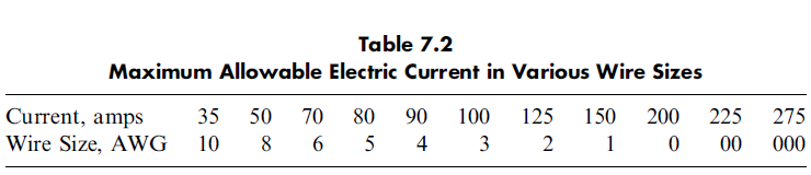
Hook-strip screens have been mounted with both underslung and overslung supports. Some previous generations of oilfield shale shaker designs used screens that were underslung, or pulled up from the bottom of a group of support, or ‘‘bucker,’’ bars (Figure 7.15). These support bars would divide the flow of material down the screen. Some problem is experienced occasionally when solids are trapped under the rubber bar supports.
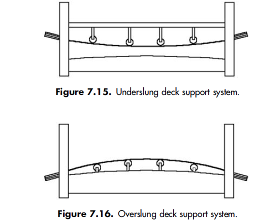
Some linear motion shale shakers utilize overslung screens (Figure 7.16). With this approach, screens are attached to the bed of the shaker by being pulled down onto the bed from the top. This results in a screening area completely free of obstacles. Modern shale shaker bed design has also increased the number of support ribs located beneath the screen to aid in fine-screen support and to reduce the amount of ‘‘crown,’’ or ‘‘bow,’’ necessary to properly tension screen panels. Some problem is experienced occasionally when the fluid leaves the high center of the screen and flows down the sides of the screen.
Most circular motion shale shakers were built with a double deck, meaning that fluid flowed over and through the top screen onto a finer screen immediately below. This arrangement led to some problems in operation, because the bottom screen was not easily visible. (Generally a flashlight was needed to inspect it.) A torn screen could remain in operation for a long time before it was noticed and changed. This created problems with solids removal because the bottom screen would not provide
the intended finer screening. Some manufacturers installed backflow pans under the top screen to direct the flow through the entire screen area of the bottom screen, but these just made it even more difficult to see the bottom screen.
Most manufacturers of linear motion shale shakers have adopted a single-deck design. The units have clear visibility for ease of care and maintenance. This unobstructed approach also makes screen changing much easier. The fluid pool tends to obscure any torn screens until drill pipe connections are made. Therefore, a torn screen on a single deck shaker reduces solids-removal efficiency until a new screen is installed.
Crews need to be alert to torn screens no matter what shaker is used. This is especially true during slow drilling, when drill pipe connections are infrequently made. When riser-assist pumps are used, flow should be periodically directed to different shakers during connections. This allows screens to be properly inspected and replaced, if needed.